
RF sim card, card reader, and communication method

a technology of rf card and card reader, applied in the field of rf card and rf card reader, and communication control methods, can solve the problems of high security risk and require calibration of communication range, and achieve the effect of reducing the shielding effect and increasing the rf communication rang

Active Publication Date: 2011-07-07
NATIONZ TECH INC
View PDF14 Cites 96 Cited by
  • Summary
  • Abstract
  • Description
  • Claims
  • Application Information

AI Technical Summary

Benefits of technology

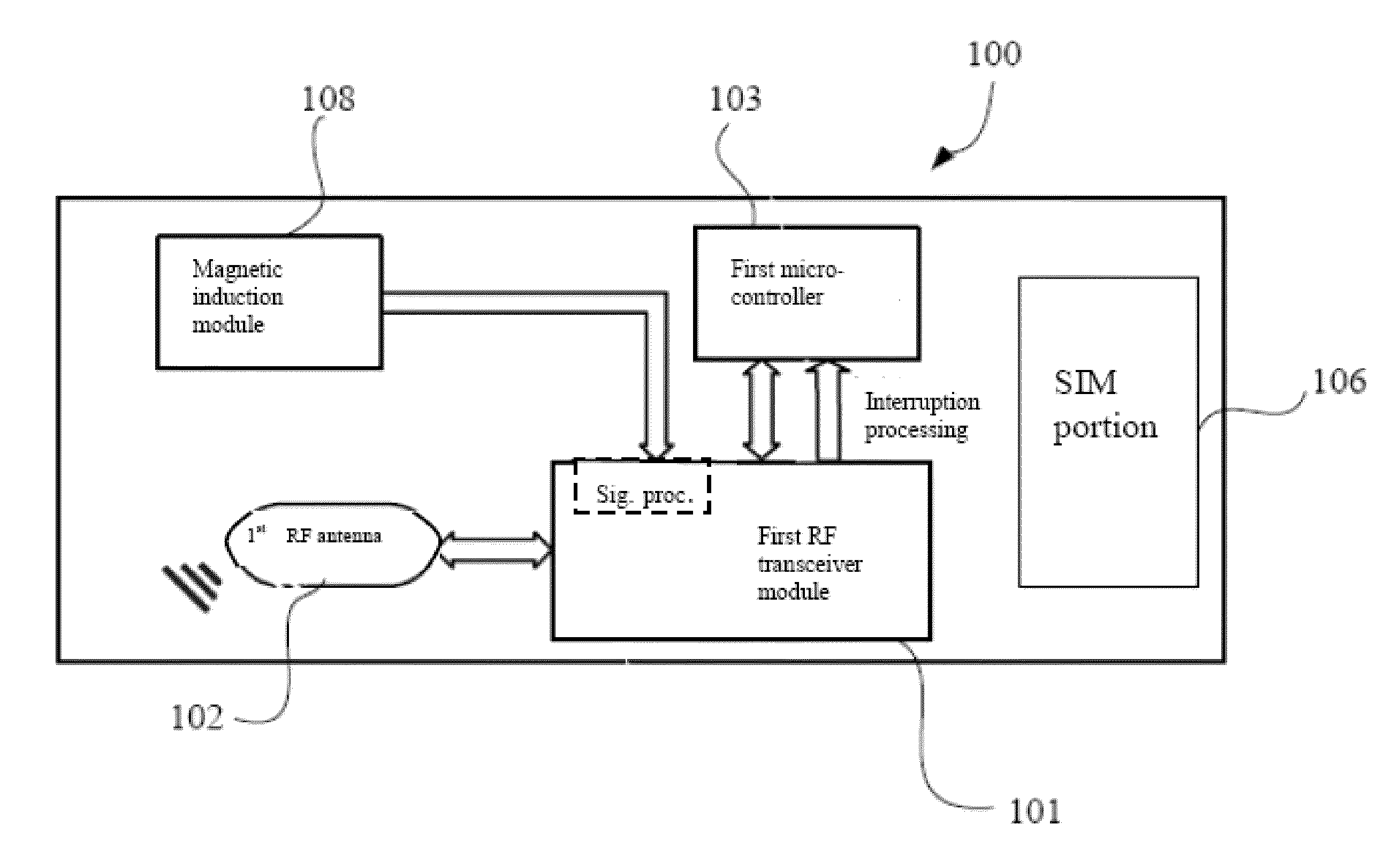
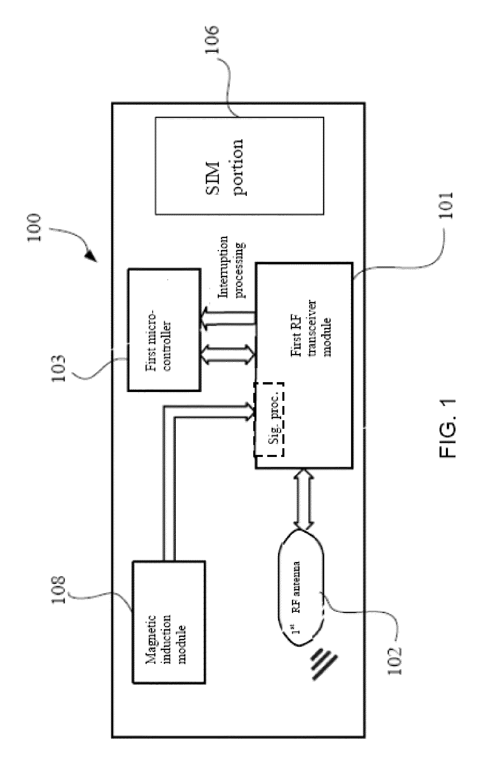
[0015]The present inventors recognized the limitations resulting from the shielding effect in the conventional 13.56 MHz technology, and have provided an RF device design, including an RF transceiver, an RF antenna, and a magnetic signal detector, that addresses these limitations and attendant disadvantages. The RF for the inventive design is selected to be in the very high frequency (VHF), ultrahigh frequency (UHF), or super high frequency (SHF) bands, such that the shielding effect is reduced and the RF device can be configured as a SIM card disposed inside a cellular phone with an increased RF communication range.
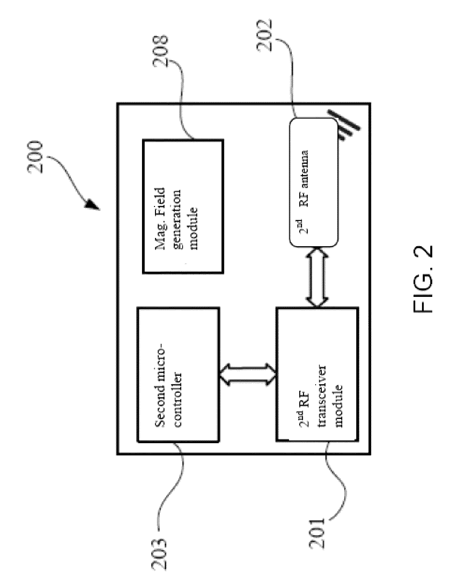
[0016]The inventors further recognize that the increased communication range afforded by the VHF, UHF, or SHF bands may lead to a higher security risk and may require calibration of the communication range. The magnetic signal detector in the RF device is used to sense a magnetic field signal from an RF reader, which includes an RF transceiver, an RF antenna, and a magnetic signal transmitter. The longer communication range afforded by the VHF, UHF, or SHF bands is reduced by the sensing of the magnetic field, thereby providing a communication range control and calibration, while the RF device and the RF reader exchange information through the RF channel with improved security as a result of the range control.

Problems solved by technology

The inventors further recognize that the increased communication range afforded by the VHF, UHF, or SHF bands may lead to a higher security risk and may require calibration of the communication range.

Method used


Image

  • RF sim card, card reader, and communication method
  • RF sim card, card reader, and communication method
  • RF sim card, card reader, and communication method

Examples


Embodiment Construction

[0089]Various integrated circuit modules can be added to SIM cards. In addition to the basic SIM function of subscriber identification, these SIM cards also can have other useful functions. Chinese Patent Application No. 200710124354.7 (now Chinese Patent no. ZL 200710124354.7) and U.S. patent application Ser. No. 12 / 837,849 (filed Jul. 16, 2010), jointly owned by the present assignee, disclose an RF SIM card that adopts active RF technologies, allowing common SIM cards to have functionalities of, for example, mobile payment, electronic wallets, access control, and other consumer applications. These documents are hereby incorporated by reference in their entirety.

[0090]An RF SIM card draws electricity from the battery of the mobile terminal, and thus will affect the standby time of the mobile terminal. A method to reduce the RF SIM card power consumption includes: the RF SIM card determines whether there is a need to proceed to exchange processing by periodically querying on whether...


PUM


Abstract

A radio frequency (RF) device includes an RF transceiver, an RF antenna, and a magnetic signal detector. The RF is selected to be in the very high frequency (VHF), ultrahigh frequency (UHF), or super high frequency (SHF) bands such that the shielding effect is reduced and the RF device can be configured as a SIM card disposed inside a cellular phone with an increased RF communication range. The magnetic signal detector is used to sense a magnetic field signal from an RF reader, which includes an RF transceiver, an RF antenna, and a magnetic signal transmitter. The longer communication range afforded by the VHF, UHF, or SHF bands is reduced by the sensing of the magnetic field, thereby providing a communication range control, while the RF device and the RF reader exchange information through the RF channel with improved security as a result of the range control.

Description

CROSS-REFERENCE TO RELATED PATENT APPLICATIONS[0001]This application is a continuation-in-part of: PCT / CN2009 / 074556 filed Oct. 22, 2009, which claims priority to Chinese Patent Application No. 200810217967.X filed Nov. 26, 2008; PCT / CN2009 / 076349 filed Dec. 31, 2009, which claim priority to Chinese Patent Application No. 200910250430.8 filed Dec. 9, 2009; and PCT / CN2010 / 071395 filed Mar. 29, 2010, which claims priority to Chinese Patent Application No. 201010300975.8 filed Jan. 29, 2010. The respective disclosures of the foregoing applications are incorporated herein by reference in their entirety.TECHNICAL FIELD[0002]The present invention involves radio frequency (RF) wireless communication technologies, particularly RF card, RF card reader and RF communication control methods.BACKGROUND[0003]The subscriber identity module (SIM) is widely used in mobile communications. Such a module is used in a mobile communication terminal in the form of a SIM card.[0004]Mobile terminals can be ...

Claims


Application Information

Patent Timeline
IPC IPC(8): H04W12/06H04M1/02
CPCH04M1/7253H04M1/72412H04W12/47
Inventor YU, YUNBOSHEN, AIMINZHU, SHANOUYANG, LILI, MEIXIANGLUO, WEIXI
Owner NATIONZ TECH INC
Learn More