Drive device for electric power conversion circuit
a technology of electric power conversion circuit and drive device, which is applied in the direction of motor/generator/converter stopper, dynamo-electric converter control, stopping arrangement, etc., can solve the problem of reducing the electric power loss generated in the power switching elemen
- Summary
- Abstract
- Description
- Claims
- Application Information
AI Technical Summary
Benefits of technology
Problems solved by technology
Method used
Image

Examples
first embodiment
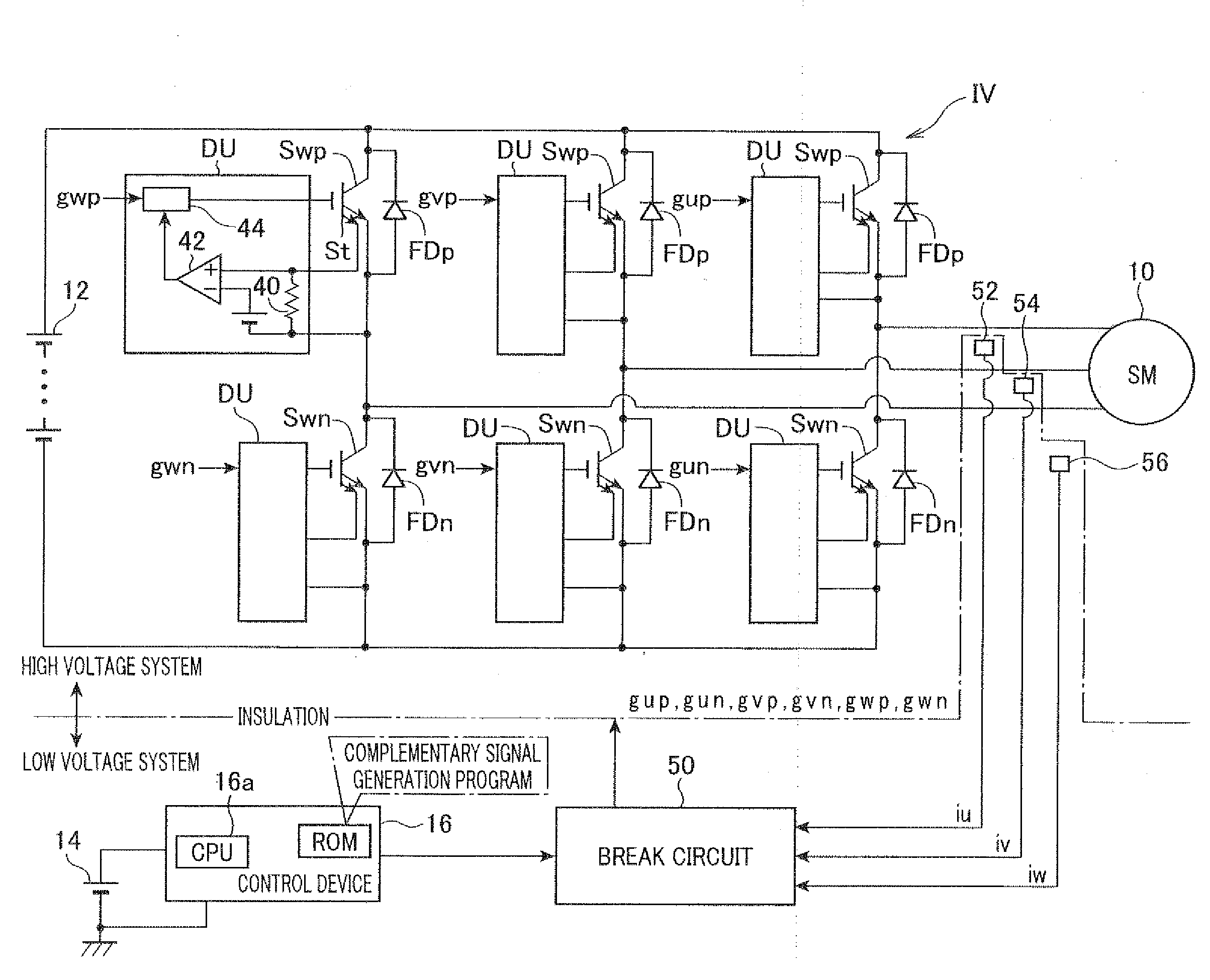
[0075]A description will be given of the control device which controls the operation of an electric power conversion circuit according to a first embodiment of the present invention with reference to FIG. 1 to FIG. 5.
[0076]FIG. 1 is a view showing a configuration of the system comprised of the motor generator 10, the inverter IV as an electric power conversion circuit, and the drive device according to the first embodiment. The drive device is comprised mainly of the control device 16, the break circuit 50, and the drive units DU. The number of the drive units DU corresponds to the number of pairs of power switching elements Sw (Swp, Swn). As will be described later, each pair is comprised of a power switching element Swp (such as an insulated gate bipolar transistor (IGBT)) in high voltage side and a powers switching element Swn such as IGBT in a low voltage side which are connected in series. The inverter IV as an electric power conversion circuit is equipped with the power switch...
second embodiment
[0130]A description will be given of the drive device according to the second embodiment of the present invention with reference to FIG. 6 and FIG. 7.
[0131]The difference in configuration between the second embodiment and the first embodiment will be explained below in detail. The explanation for the same components between the second embodiment and the first embodiment is omitted here.
[0132]FIG. 6 is a view showing another configuration of the system comprised of the motor generator 10, the inverter IV as an electric power conversion circuit, and the drive device according to the second embodiment. The drive device according to the present invention is comprised mainly of the control device 16 and the drive units DU without the break circuit 50.
[0133]That is, as shown in FIG. 6, the drive device according to the second embodiment is composed mainly of the control device 16 and the drive units DU without the break circuit 50. The break circuit 50 is used in the system of the first e...
third embodiment
[0153]A description will be given of the drive device according to the third embodiment of the present invention with reference to FIG. 8 to FIG. 12.
[0154]FIG. 8 is a view showing a configuration of the system comprised of the motor generator 10, the inverter IV as an electric power conversion circuit, and the drive device according to the third embodiment of the present invention.
[0155]The drive device according to the third embodiment is comprised mainly of the break circuit 50, the control device 16, and the drive units DU. The inverter IV as an electric power conversion circuit is equipped with power switching elements Sw (Swp, Swn). The power switching elements Sw (Swp, Swn) are controlled in operation by the drive device according to the third embodiment.
[0156]As shown in FIG. 8, the motor generator 10 as the on-vehicle main device is electrically connected to the high voltage battery 12 through the inverter IV. The inverter IV is comprised of three pairs of power switching el...
PUM
 Abstract
Description
Claims
Application Information
 - R&D
- Intellectual Property
- Life Sciences
- Materials
- Tech Scout
- Unparalleled Data Quality
- Higher Quality Content
- 60% Fewer Hallucinations
Browse by: Latest US Patents, China's latest patents, Technical Efficacy Thesaurus, Application Domain, Technology Topic, Popular Technical Reports.
© 2025 PatSnap. All rights reserved.Legal|Privacy policy|Modern Slavery Act Transparency Statement|Sitemap|About US| Contact US: help@patsnap.com