
Contact device for insulation displacement connector

a contact device and connector technology, applied in the direction of coupling device connection, contact member manufacturing, contact member penetration/cutting of insulation/cable strand, etc., can solve the problem of difficulty in providing such a system

Active Publication Date: 2009-05-05
ASLAN INDS
View PDF9 Cites 2 Cited by
  • Summary
  • Abstract
  • Description
  • Claims
  • Application Information

AI Technical Summary

Benefits of technology

[0009](c) a bridge portion connecting said first blade to said second blade and securing said second blade portion in a spaced apart relationship with said first blade portion whereby, when said contact device is pushed into a multi-conductor cable, said first contact portion is in electrical contact with a first side of a solid wire conductor and said front angled portion is in electrical contact with a second side of said solid wire conductor. With this arrangement said solid wire conductor is disposed between said first contact portion and said front angled portion to form a reliable electrical connection.
[0016]Preferably, said contact device also includes an insulating fin member juxtaposed tightly against an opposite surface of said front contact portion said insulating fin adapted to remove at least a portion of insulation from said solid wire conductor. Preferably, said first blade portion and said second blade portion will help remove any insulation on the solid wire conductor not removed by the insulating fin.

Problems solved by technology

While various devices teach the piercing of an unstripped end of an electric cable to make electrical connections with insulated solid wire conductors, in practice, it is extremely difficult to provide such a system which reliably makes secure and adequate connections with not only the ground wire but also with the hot and neutral wires.

Method used


Image

  • Contact device for insulation displacement connector
  • Contact device for insulation displacement connector
  • Contact device for insulation displacement connector

Examples


Embodiment Construction

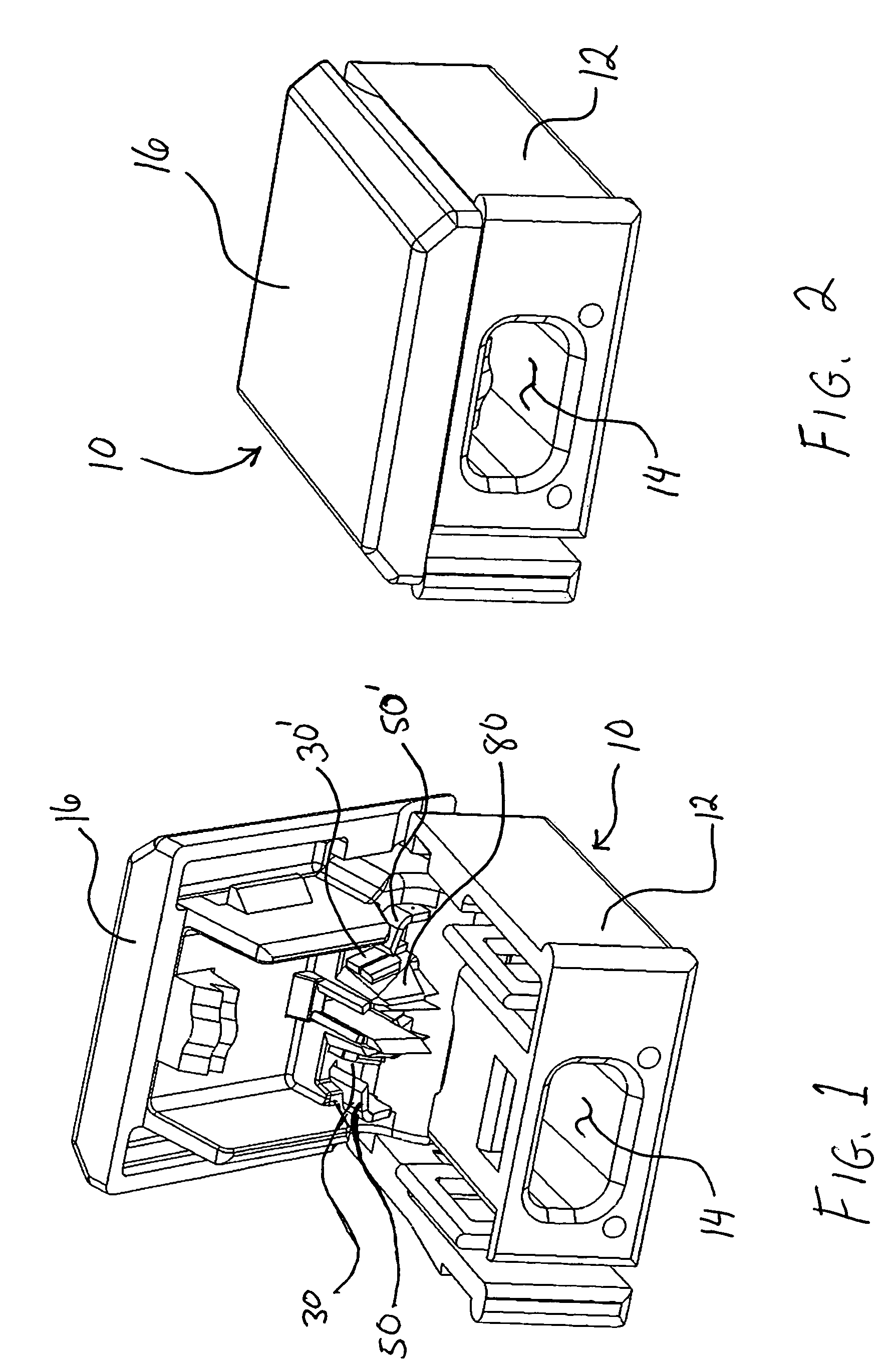
[0032]Referring first to FIGS. 1, 2 and 11, the present invention provides an insulated displacement connector for quickly and easily connecting an unstripped end of an electrical cable 300 to the displacement connector. FIG. 1 shows the insulated displacement connector 10 which has a base portion 12 into which an opening 14 is provided so as to allow the insertion of a cable 300. FIG. 1 shows the connector 10 having a lid 16 in an open position. On the lower surface of the lid 16, a pair of first blade portions 30 and 30′ and a pair of the second blade portions 50 and 50′ are shown.

[0033]FIG. 2 shows the displacement connector 10 with the lid 16 in a closed position. FIG. 11 shows the sequence by which a cable 300 is inserted in to opening 14 with the lid in an open position and the closing of the lid 16 to a closed position by means of plier device 400.

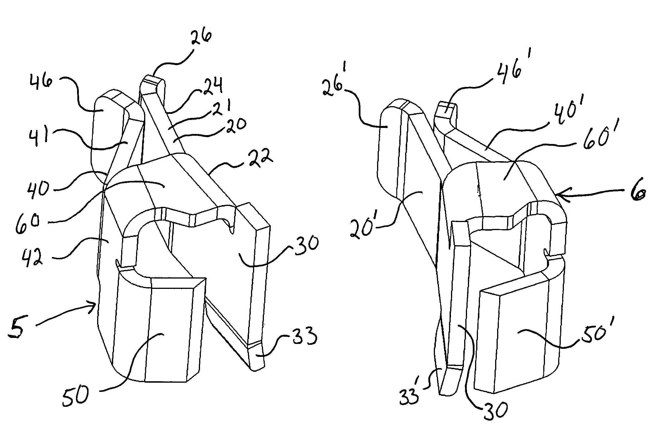
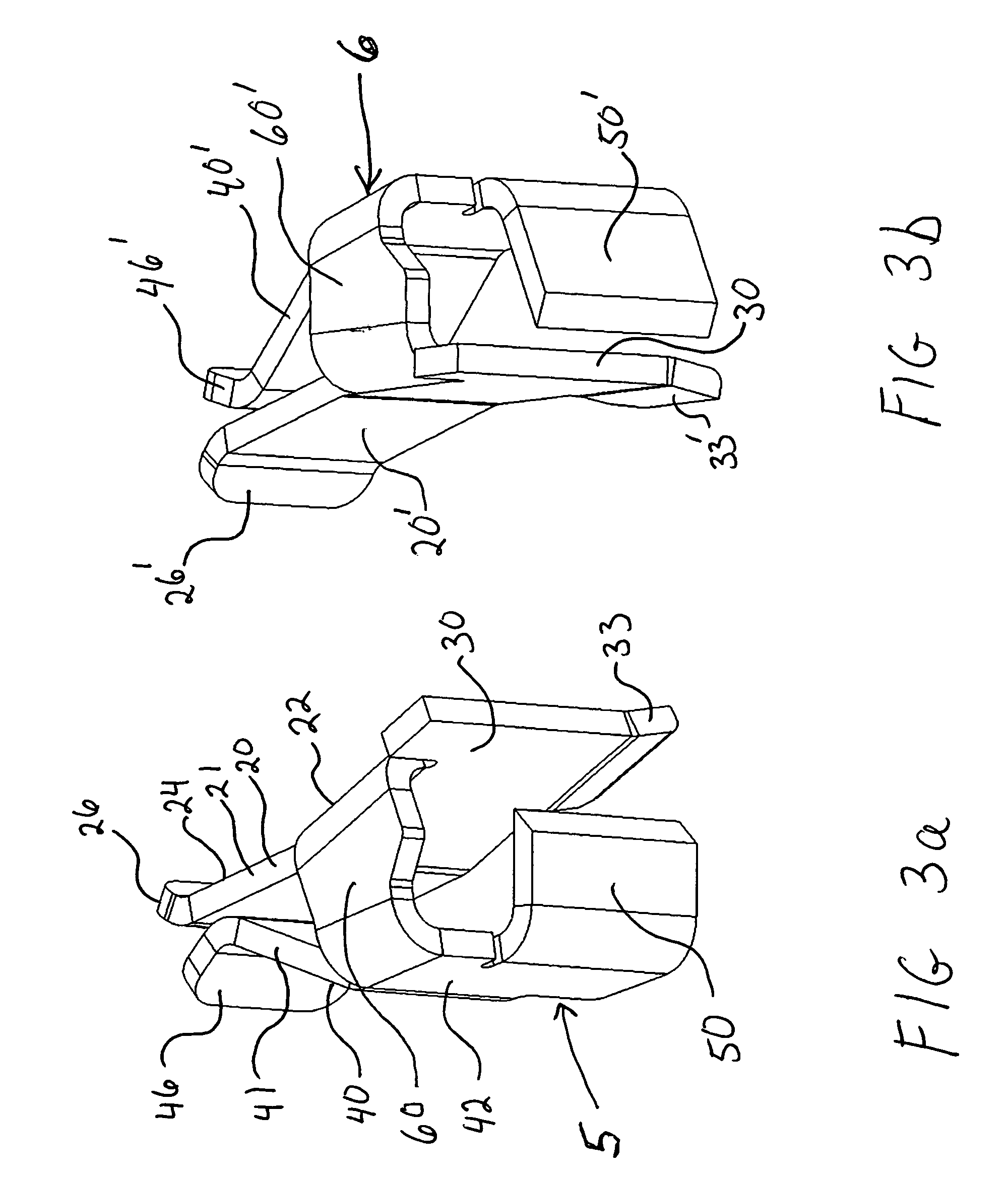
[0034]Referring now to FIG. 3a and FIG. 3b, various details of the contact device are shown. Initially, contact device 5 (as shown...


PUM


Abstract

A contact device for insulated solid conductors of an insulation displacement connector of the type utilized to make electrical connections with an unstripped end of a multi-conductor cable having an outer sheath enclosing a ground wire and at least two insulated solid wire conductors is disclosed. A first blade portion has a front contact portion, a first blade middle portion and a first blade rear receiving end. A second blade portion has a front angled blade portion, a second blade middle portion and a second blade rear receiving end. A bridge portion connects the first blade to the second blade and secures the second blade portion in a spaced apart relationship with respect to the first blade portion. With this arrangement when the contact device is pushed into a multi-conductor cable, the first contact portion is in electrical contact with a first side of a solid wire conductor and the front angled portion is in electrical contact with a second side of the solid wire conductor. Thus, the solid wire conductor is disposed between the first contact portion and the front angled portion to form and maintain a more reliable electrical connection even when expansion or contraction or some movement of the solid wire conductor or components of the contact device might occur.

Description

FIELD OF THE INVENTION[0001]The present invention relates to a metallic contact device for insulated cable. More specifically, it relates to a manufactured metallic contact device having spaced apart arms to make reliable electrical connections with an unstripped end of a multi-conductor cable having an outer sheath enclosing a ground wire and at least two insulated solid wire conductors.DESCRIPTION OF THE PRIOR ART[0002]The purpose of an insulation displacement connector (IDC) is to make an electrical connection between the metallic conductors of an insulated cable and the metallic contacts in a connector. This is done to transfer electric current from the current carrying cable to a connector which then delivers current to any device or another cable. IDC's eliminate the need to manually strip insulation from electrical conductors and further eliminates the use of wire nuts to terminate these conductors.[0003]Prior to the present invention, various connection devices have been pro...

Claims


Application Information

Patent Timeline
Patent Type & Authority Patents(United States)
IPC IPC(8): H01R4/24
CPCH01R4/2412H01R9/031H01R13/113H01R43/16
Inventor LIBBY, ROBERT A.
Owner ASLAN INDS
Learn More