
Noise suppression in cone beam ct projection data

a cone beam and projection data technology, applied in the field of diagnostic imaging, can solve the problems of increasing the overall acquisition time, delivering a higher dose of x-ray to the patient, and affecting many automated image processing and analysis tasks, so as to reduce the tangential blur in image reconstruction and suppress the noise

Inactive Publication Date: 2011-06-23
CARESTREAM DENTAL TECH TOPCO LTD
View PDF3 Cites 15 Cited by
  • Summary
  • Abstract
  • Description
  • Claims
  • Application Information

AI Technical Summary

Benefits of technology

[0022]It is an advantage of the present invention that it reduces tangential blur in image reconstruction.
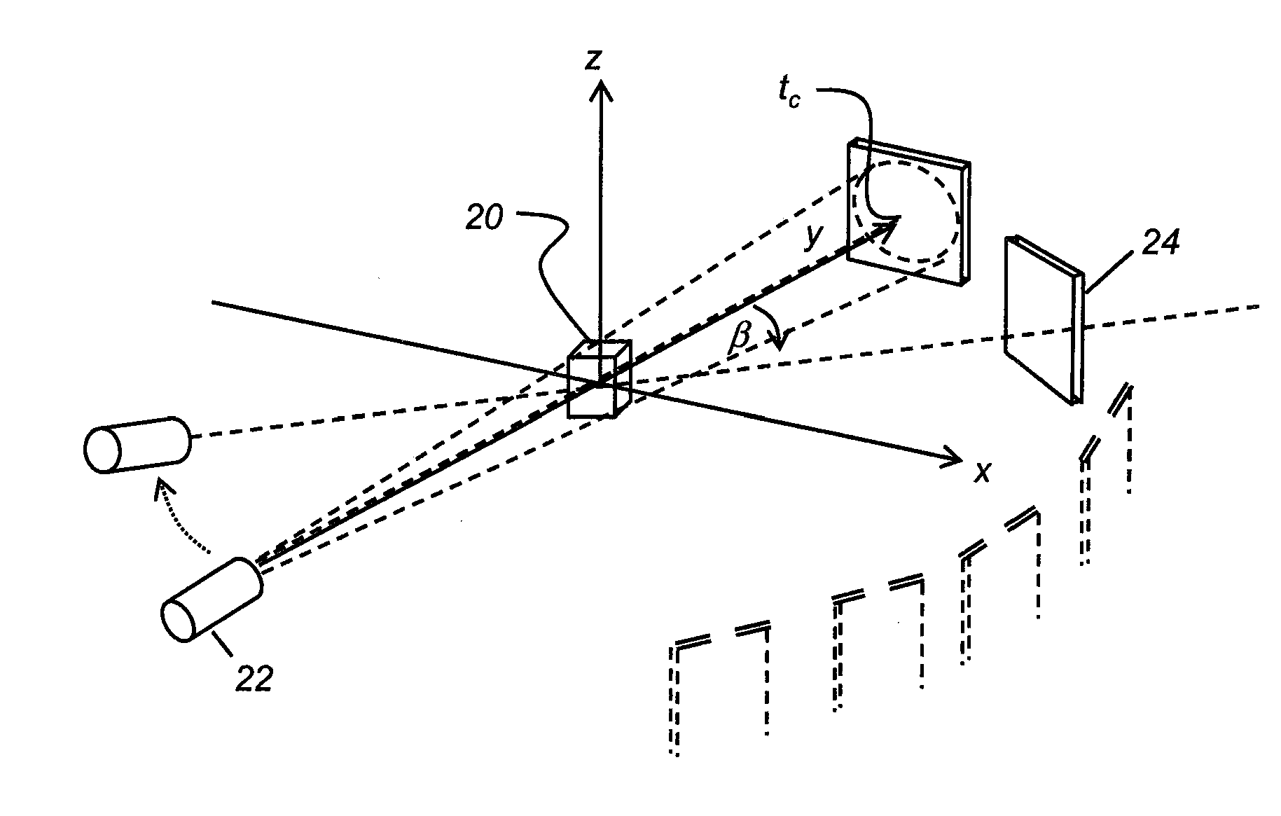
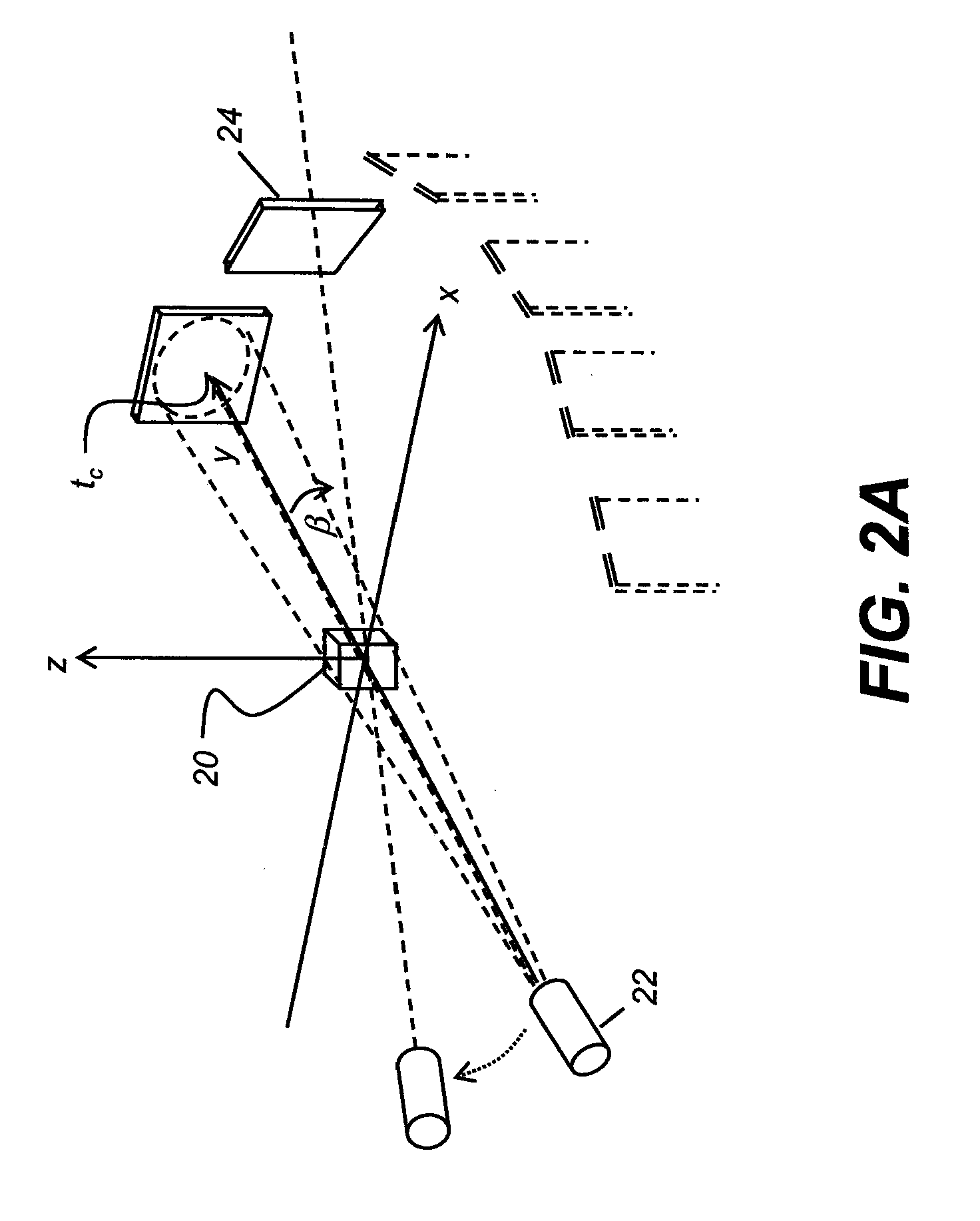
[0023]From one aspect, the present invention provides a method for suppressing noise in a diagnostic 3-D image, the method executed at least in part on a logic processor and comprising: capturing at each of a plurality of projection angles, 2-D image projection data, wherein each 2-D image projection has a central pixel; arranging the captured 2-D image projection data in an electronic memory to form a 3-D data set; processing the image projection data for each of the 2-D image projections of the 3-D data set by performing a diffusion filtering process that comprises: obtaining a homogeneity value for the 3-D data set; generating a diffusion conductance function according to an intensity gradient between adjacent digital image elements from the projection data; applying the diffusion filtering process to a plurality of digital image elements according to the obtained homogeneity value, the generated diffusion conductance function, and a weighting value that relates to the distance of each pixel in the projection from the central pixel; and reconstructing the diagnostic 3-D image from the processed 2-D image projection data.

Problems solved by technology

In addition to influencing diagnostic functions, noise also affects many automated image processing and analysis tasks that are crucial in a number of diagnostic applications.
Improving image acquisition techniques beyond a certain point can introduce other problems and generally requires increasing the overall acquisition time.
This risks delivering a higher X-ray dose to the patient and loss of spatial resolution and may require the expense of scanner equipment upgrade.
This can be especially troublesome because details of particular interest often lie along an edge or a boundary of a structure within the image, which can be blurred by conventional smoothing operations.
While such an approach exhibits some success with 2-D images, however, there are drawbacks.
One shortcoming of this type of solution relates to the lack of image-dependent guidance for selecting a suitable gradient magnitude.
More particularly, since morphological or structural information is not used to locally control the extent of diffusion in different regions, fine structures often disappear and boundaries that are initially somewhat fuzzy may be further blurred upon filtering when this technique is used.
Three-dimensional imaging introduces further complexity to the problem of noise suppression.
However, image noise remains a problem.
Using conventional diffusion techniques to reduce image noise can often blur significant features within the 3-D image, making it disadvantageous to perform more than rudimentary image clean-up for reducing noise content.
The widely used Grangeat algorithm, familiar to those skilled in CBCT image processing, is limited to circular scanning trajectory and spherical objects.
The discrete nature of the x-ray exposure and its conversion to a detected signal invariably results in quantum noise fluctuations.
A second source of image noise is the flat-panel detector and signal readout circuits.
In practice, however, several external factors, such electro-magnetic interference, can influence both the magnitude and the spatial correlations of image noise due to the detector.
However, as compared against 2-D considerations, the 3-D noise problem is significantly more complex and does not readily lend itself to 2-D solutions.

Method used


Image

  • Noise suppression in cone beam ct projection data
  • Noise suppression in cone beam ct projection data
  • Noise suppression in cone beam ct projection data

Examples


Embodiment Construction

[0039]The following is a detailed description of the preferred embodiments of the invention, reference being made to the figures in which the same reference numerals identify the same elements of structure in each of the figures.

[0040]The term “image element” or “digital image element” refers to a pixel (from “picture element” and commonly used for an image with two dimensions) or to a voxel (from “volume picture element” for an image of three or more dimensions). In CBCT imaging, the two types of digital image elements are closely related: 3-D voxels are formed using data obtained from pixels that were obtained in one or more 2-D projections. The terms “in-plane” and “out-of-plane” relate to the arrangement of image element data as obtained from the planar 2-D digital detector and used to form 3-D voxels.

[0041]The term “region” is used in the present application to describe an area of a 2-D image or, correspondingly, a volume of a 3-D or 4-D or higher image that contains a grouping...


PUM


Abstract

A method for suppressing noise in a diagnostic 3-D image, executed at least in part on a logic processor, captures, at each of a number of projection angles, 2-D image projection data, wherein each 2-D image projection has a central pixel and arranges the 2-D image projection data to form a 3-D data set. Each of the 2-D image projections is processed by performing a diffusion filtering process that obtains a homogeneity value for the 3-D data set, generates a diffusion conductance function according to an intensity gradient between adjacent digital image elements, and applies the diffusion filtering process to digital image elements according to the obtained homogeneity value, the generated diffusion conductance function, and a weighting value that relates to the distance of each pixel in the projection from the central pixel. The diagnostic 3-D image is reconstructed from the processed 2-D image projections.

Description

FIELD OF THE INVENTION[0001]The invention relates generally to the field of diagnostic imaging and more particularly relates to a method for noise suppression for images obtained from cone-beam projection data.BACKGROUND OF THE INVENTION[0002]Noise is often present in acquired diagnostic images, such as those obtained from computed tomography (CT) scanning and other x-ray systems, and can be a significant factor in determining how well real intensity interfaces and fine details are preserved in the image. In addition to influencing diagnostic functions, noise also affects many automated image processing and analysis tasks that are crucial in a number of diagnostic applications.[0003]Methods for improving signal-to-noise ratio (SNR) and contrast-to-noise ratio (CNR) can be broadly divided into two categories: those based on image acquisition techniques and those based on post-acquisition image processing. Improving image acquisition techniques beyond a certain point can introduce oth...

Claims


Application Information

Patent Timeline
IPC IPC(8): G06K9/40G06K9/00
CPCG06T5/002G06T11/005A61B6/027G06T7/0012A61B6/5258G06T2207/10081G06T5/70
Inventor SOUZA, ANDREBURNS, PETER D.
Owner CARESTREAM DENTAL TECH TOPCO LTD
Learn More