Tool for machining, in particular longitudinal turning tool

a technology for turning tools and machining, applied in the direction of turning tools, turning apparatus, cutting inserts, etc., can solve the problem of little space available for replacing cutting tools, and achieve the effect of simple design

Active Publication Date: 2011-06-16
HARTMETALL WERKZEUGFAB PAUL HORN
View PDF8 Cites 4 Cited by
  • Summary
  • Abstract
  • Description
  • Claims
  • Application Information

AI Technical Summary

Benefits of technology

[0005]The present invention is based on the object of presenting a tool, having an exchangeable cutting tool, which enables the fastening means to be tightened or undone from differing sides, wherein, however, the fastening means are of simple design, and wherein the same auxiliary tool can always be used, irrespective of the side from which the fastening means are tightened or undone.
[0008]Consequently, irrespective of the side on which the clamping screw is located, in each case only one and the same tool is required for tightening or undoing the clamping screw. Further, the fastening means used according to the invention can be produced very easily, and therefore cost-effectively. An internal thread is not provided within the tool-body bore on the tool body itself, as in the case of the conventionally applied solution, merely a simple bore being provided instead. Likewise, in the case of the invention, merely a simple bore is provided on the cutting tool, rather than support wings that are complicated, and therefore expensive, to produce, as in the case of the solution known from WO 2003 / 074217, such that, in comparison with this cutting tool, the cutting tool used according to the invention, which is subject to frequent wear, can be produced with significantly greater cost-effectiveness.
[0011]In principle, there are a range of possibilities for preventing the clamping bushing from rotating as the clamping screw is being tightened or undone. In a development, provision is made for this purpose whereby the anti-rotation means and at least a portion of the tool-body bore have a cross-section that prevents rotation of the clamping bushing when it has been inserted into the tool body. This, likewise, constitutes a possibility that is technically simple and that therefore can be realized cost-effectively, which can be applied in addition to the securing bolt described above or as an alternative thereto. In particular, provision is made whereby the anti-rotation means and at least a portion of the tool body have a non-circular cross-section, in particular an oval or angular cross-section, or a cross-section flattened on at least one side. In principle in this case, any form of the cross-section that reliably prevents the clamping bushing from rotating during tightening or undoing can be used.

Problems solved by technology

However, in the case of automated longitudinal turners, in which such tools, so-called longitudinal turning tools, are frequently used, there is often little space available for replacing the cutting tool, which is a wearing part and has to be changed frequently, while the tool body remains clamped into the machine tool.

Method used


Image

  • Tool for machining, in particular longitudinal turning tool
  • Tool for machining, in particular longitudinal turning tool
  • Tool for machining, in particular longitudinal turning tool

Examples


Embodiment Construction

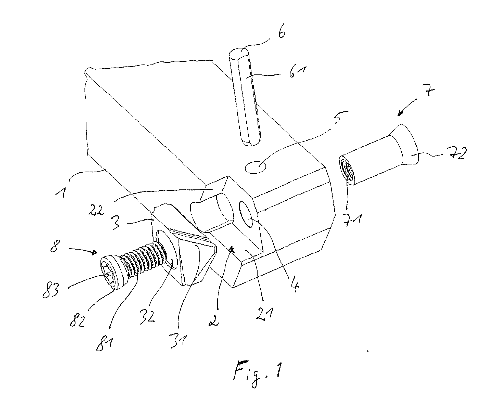
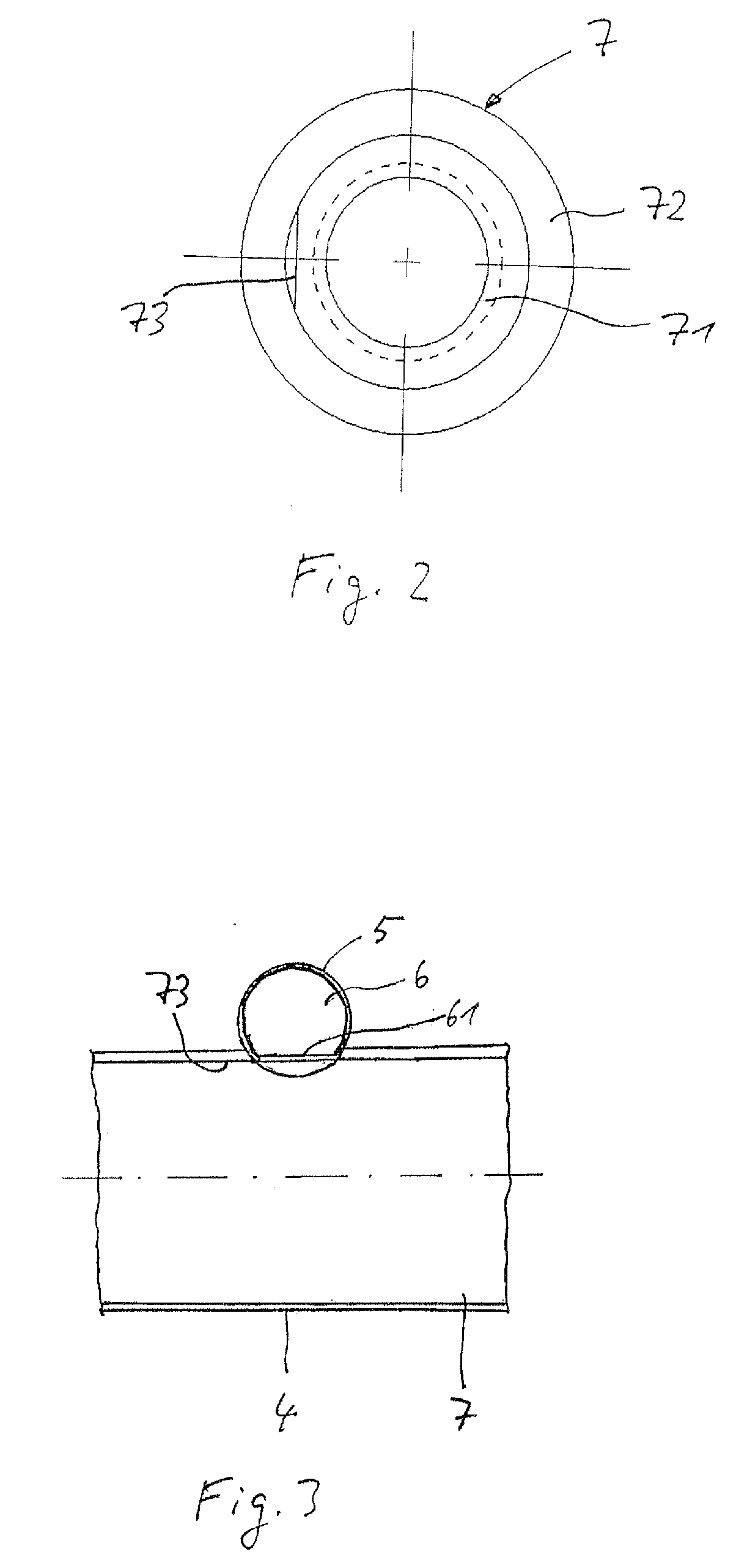
[0024]FIG. 1 shows a first design of the tool according to the invention, in a disassembled state. It shows the tool body 1, provided at the front lateral end of which there is a receiving recess 2 for receiving a cutting tool 3. A tool-body bore 4, which opens into the receiving recess 2, is provided transversely in the front region of the tool body 1. Further, a securing bore 5, for receiving a securing pin, or securing bolt, 6, is arranged transversely relative to the tool-body bore 4, extending at right angles thereto and intersecting the tool-body bore 4 in the case of this exemplary embodiment.

[0025]The cutting tool 3, being, in the present case, a reversible cutting bit having two cutting edges 31 (the rear cutting edge is not visible in this representation), has a cutting-tool through-bore 32 in its center.

[0026]According to the invention, a clamping bushing 7 and a clamping screw 8 are provided as fastening means for fastening the cutting tool 3 in the receiving recess 2. T...


PUM


Abstract

The present invention relates to a tool for machining a workpiece, comprising a tool body, a cutting tool, and fastening means for fastening the cutting tool in a receiving recess of the tool body, the cutting tool having a cutting edge and a cutting-tool through-bore, and the tool body having a tool-body through-bore that opens into the receiving recess, wherein the fastening means comprises a clamping bushing that is provided with an internal thread, and comprises a clamping screw that is provided with an external thread corresponding to the internal thread of the clamping bushing, which are inserted into the cutting-tool bore or into the tool-body bore from opposing sides in order to fasten the cutting tool to the tool body, the clamping bushing is screwed directly to the clamping screw, irrespective of whether it is inserted into the cutting-tool bore or into the tool-body bore, and anti-rotation means are provided to prevent the clamping bushing from rotating about its longitudinal axis when being screwed and undone by means of the clamping screw.

Description

CROSS-REFERENCE TO RELATED APPLICATIONS[0001]This is a continuation application of International patent application PCT / EP2008 / 009965, filed Nov. 25, 2008, designating the United States and published as WO 2009 / 077060 A1, which claims priority to German application no. 10 2007 063 199.7, filed on Dec. 19, 2007, both of which are hereby incorporated by reference herein in their entirety, including any figures, tables, or drawings.FIELD OF THE INVENTION[0002]The present invention relates to a tool for machining a workpiece, comprising a tool body, a cutting tool, and fastening means for fastening the cutting tool in a receiving recess of the tool body, the cutting tool having a cutting edge and a cutting-tool through-bore, and the tool body having a tool-body through-bore that opens into the receiving recess. The present invention relates, in particular, to a longitudinal turning tool.BACKGROUND OF THE INVENTION[0003]In the case of known tools, the cutting tool, for example a cutting ...

Claims


Application Information

Patent Timeline
IPC IPC(8): B23B27/16
CPCY10T407/1936B23B2205/04B23B27/1614Y10T407/2274
Inventor OETTLE, MATTHIASRUOFF, ULI
Owner HARTMETALL WERKZEUGFAB PAUL HORN
Why Eureka
Try Eureka