
Method and apparatus interleaving pixel of reference image within single bank of frame memory, and video codec system having the same

a video codec and reference image technology, applied in the field of video codec systems having the same, can solve the problems of increasing cas latency (cl) and large amount of pixel data, and requiring more delay time to read data

Inactive Publication Date: 2011-06-16
ELECTRONICS & TELECOMM RES INST
View PDF10 Cites 3 Cited by
  • Summary
  • Abstract
  • Description
  • Claims
  • Application Information

AI Technical Summary

Benefits of technology

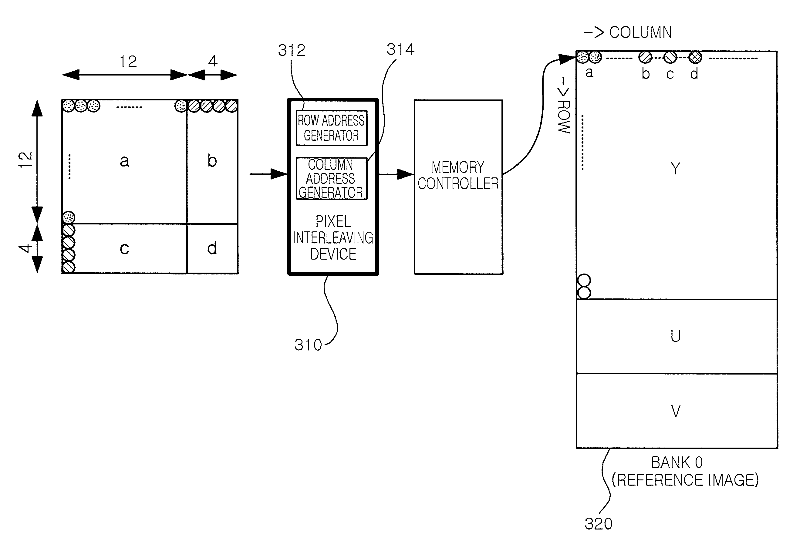
[0011]An aspect of the present invention provides a method and apparatus for interleaving pixels of a reference image within a single bank of a frame memory capable of solving the problem of a degradation of the performance of an overall system due to latency (tRCD+CL) potentially generated in reading a reference image, which is required for a motion estimation or motion compensation in processing an image, from a frame memory such as an SDRAM or a DDR SDRAM, and a video codec system having the same.
[0012]Another aspect of the present invention provides a method and apparatus for interleaving pixels of a reference image within a single bank of a frame memory capable of minimizing a memory read latency (TREAD) while using a general single-port memory controller, rather than a special multi-port memory controller, and improving the performance of an overall video codec by securing a memory bandwidth, and a video codec system having the same.

Problems solved by technology

However, because the amount of pixel data is large, a large capacity frame memory such as an SDRAM or a DDR SDRAM is used.
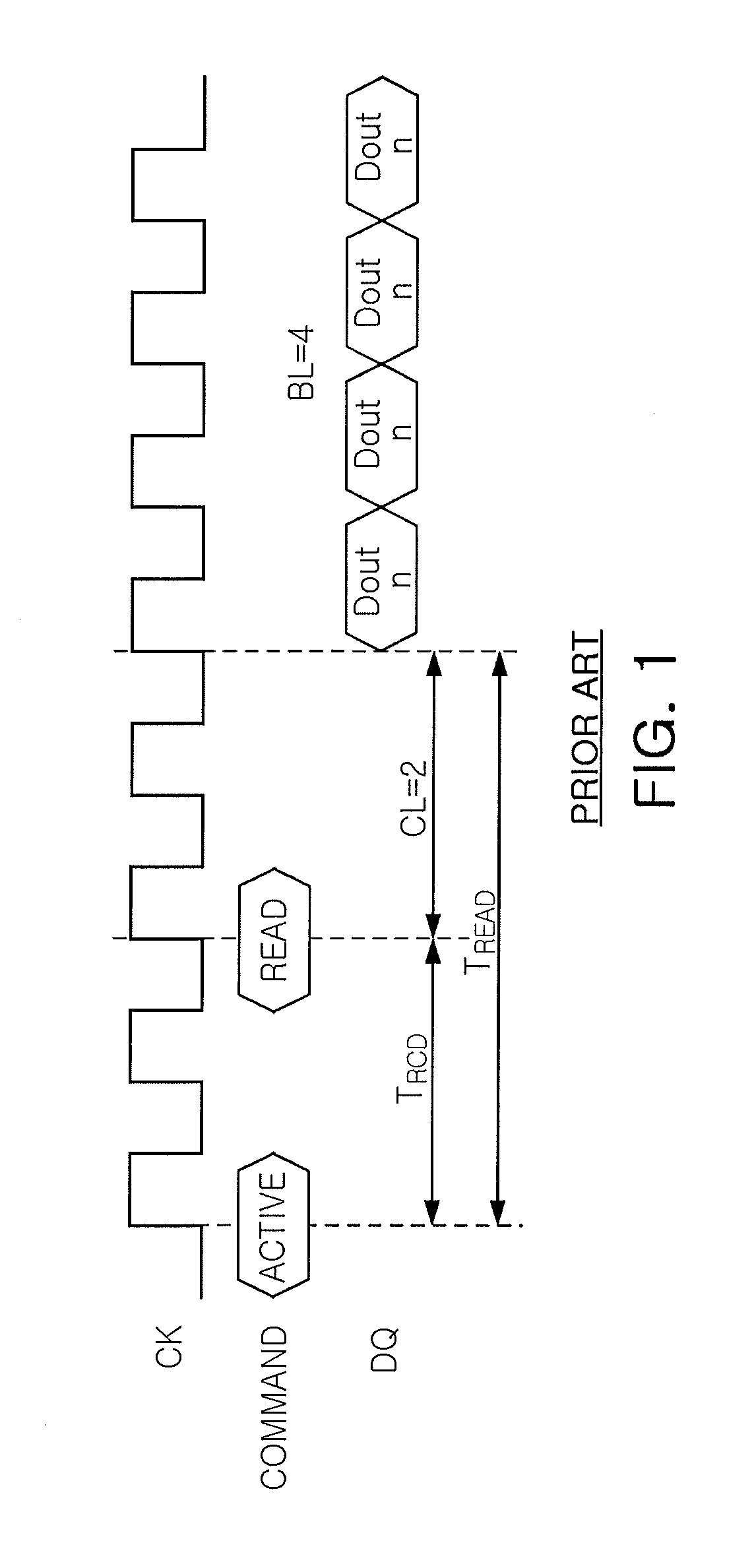
Unlike an SRAM, this requires a delay time of TREAD (tRCD+CL) in reading data, and as a clock frequency increases, the CAS latency (CL) also increases, causing a problem in that more delay time is required to read data.
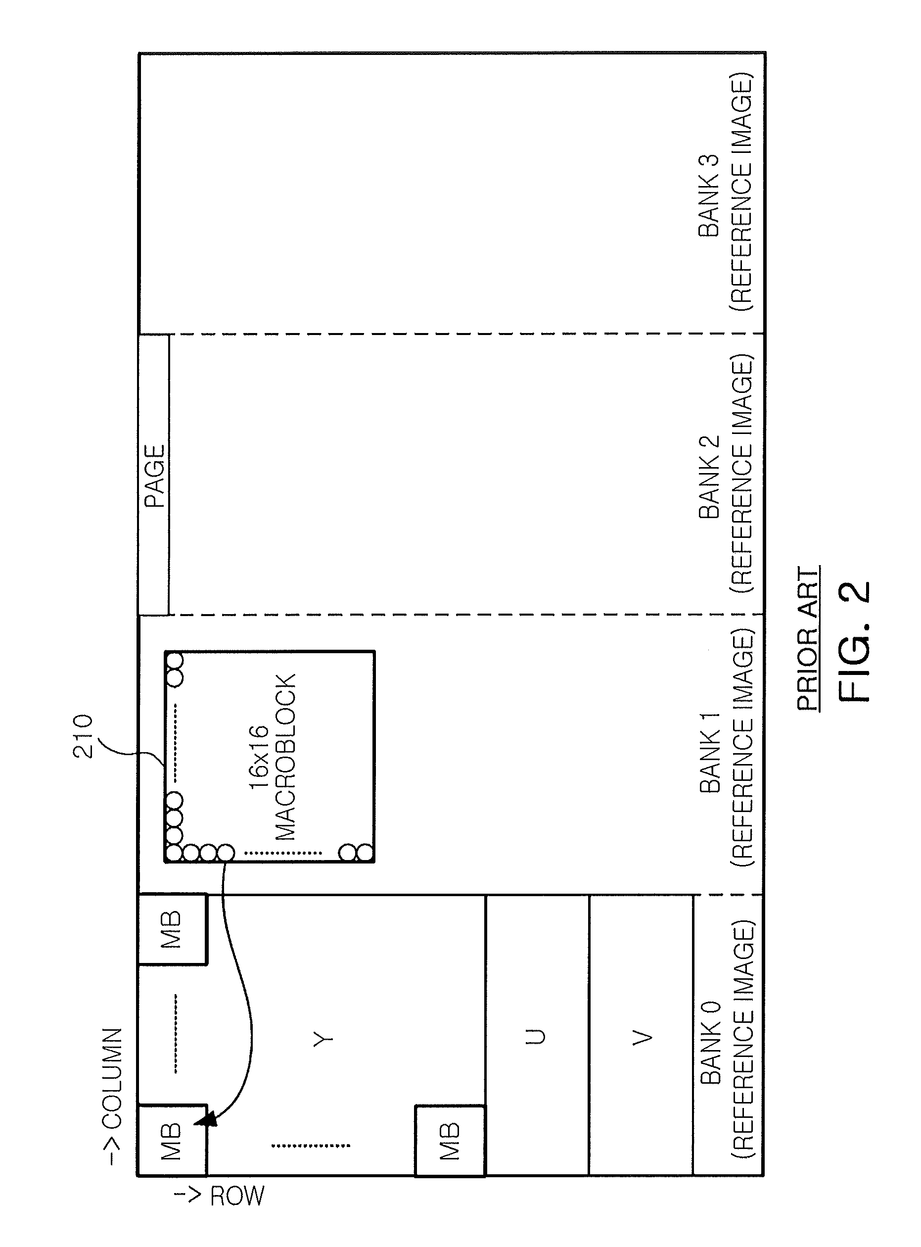
However, the effect of multi-bank interleaving is reduced when a burst length is smaller than a CL cycle, which, thus, requires a special multi-port memory controller supporting multi-bank interleaving, unlike a general memory controller, and this leads to additional complexity in implementation.

Method used


Image

  • Method and apparatus interleaving pixel of reference image within single bank of frame memory, and video codec system having the same
  • Method and apparatus interleaving pixel of reference image within single bank of frame memory, and video codec system having the same
  • Method and apparatus interleaving pixel of reference image within single bank of frame memory, and video codec system having the same

Examples


Embodiment Construction

[0025]Exemplary embodiments of the present invention will now be described in detail with reference to the accompanying drawings. The invention may, however, be embodied in many different forms and should not be construed as being limited to the embodiments set forth herein. Rather, these embodiments are provided so that this disclosure will be thorough and complete, and will fully convey the scope of the invention to those skilled in the art. In the drawings, the shapes and dimensions may be exaggerated for clarity, and the same reference numerals will be used throughout to designate the same or like components.

[0026]FIG. 1 is a view for explaining a delay time (or latency) generated in reading data from a general frame memory.

[0027]With reference to FIG. 1, when data is read from a large capacity frame memory such as an SDRAM memory or a DDR SDRAM, a read command (READ) defining a burst length (BL) and a memory address is given after the lapse of a certain time of read latency (tR...


PUM


Abstract

A method and apparatus for interleaving pixels of a reference frame within a single bank of a frame memory in a video codec, and a video codec system including the same are provided. The method for interleaving pixels of a reference image within a single bank of a frame memory includes: interleaving pixel data of a reference image as a filter output of a restoration image required for video processing by column of a macro block; and storing the interleaved pixel data within a single bank of a frame memory by page.

Description

CROSS-REFERENCE TO RELATED APPLICATIONS[0001]This application claims the priority of Korean Patent Application No. 10-2009-0122188 filed on Dec. 10, 2009, in the Korean Intellectual Property Office, the disclosure of which is incorporated herein by reference.BACKGROUND OF THE INVENTION[0002]1. Field of the Invention[0003]The present invention relates to a method and apparatus for interleaving pixels of a reference frame within a single bank of a frame memory in a video codec, and a video codec system having the same.[0004]2. Description of the Related Art[0005]A reference image is a result value obtained by creating a reconstruction image by adding a decoded residual value to an image formed through inter-prediction or intra-prediction and then deblocking-filtering the reconstruction image in order to reduce distortion between macro blocks according to a video codec. Here, the reference image is re-used in the event of inter-prediction of a next frame, and the size of the created re...

Claims


Application Information

Patent Timeline
IPC IPC(8): H04N11/04H04N19/593
CPCH04N19/433H04N19/423
Inventor LEE, SUK HOPARK, SEONG MOCHO, SEUNG HYUNEUM, NAK WOONG
Owner ELECTRONICS & TELECOMM RES INST
Learn More