
Thermal energy storage and transfer assembly and method of making same

a technology of thermal energy storage and transfer, which is applied in the manufacture of electrode systems, x-ray tubes, and electric discharge tubes/lamps, etc., can solve the problems of inefficient process, high thermal stress on x-ray tube components, and addition of heating of x-ray tubes

Active Publication Date: 2011-06-09
GENERAL ELECTRIC CO
View PDF4 Cites 5 Cited by
  • Summary
  • Abstract
  • Description
  • Claims
  • Application Information

AI Technical Summary

Problems solved by technology

Additionally, some of the electrons back scatter from the target and impinge on other components within the vacuum vessel, causing additional heating of the x-ray tube.
As a result of the high temperatures caused by this thermal energy, the x-ray tube components are subject to high thermal stresses.
Since the production of x-rays in a medical diagnostic x-ray tube is by its nature a very inefficient process, the components in x-ray generating devices operate at elevated temperatures.
The excessive temperatures that build up within the x-ray tube can decrease the life of the transmissive window, as well as other x-ray tube components.
Due to its close proximity to the focal spot, the x-ray transmissive window is subject to very high heat loads resulting from thermal radiation and back scattered electrons.
The high heat loads cause very large and cyclic stresses in the transmissive window and can lead to premature failure of the window and its hermetic seals.
These approaches, however, often do not adequately minimize thermal stress on the transmissive window.

Method used


Image

  • Thermal energy storage and transfer assembly and method of making same
  • Thermal energy storage and transfer assembly and method of making same
  • Thermal energy storage and transfer assembly and method of making same

Examples


Embodiment Construction

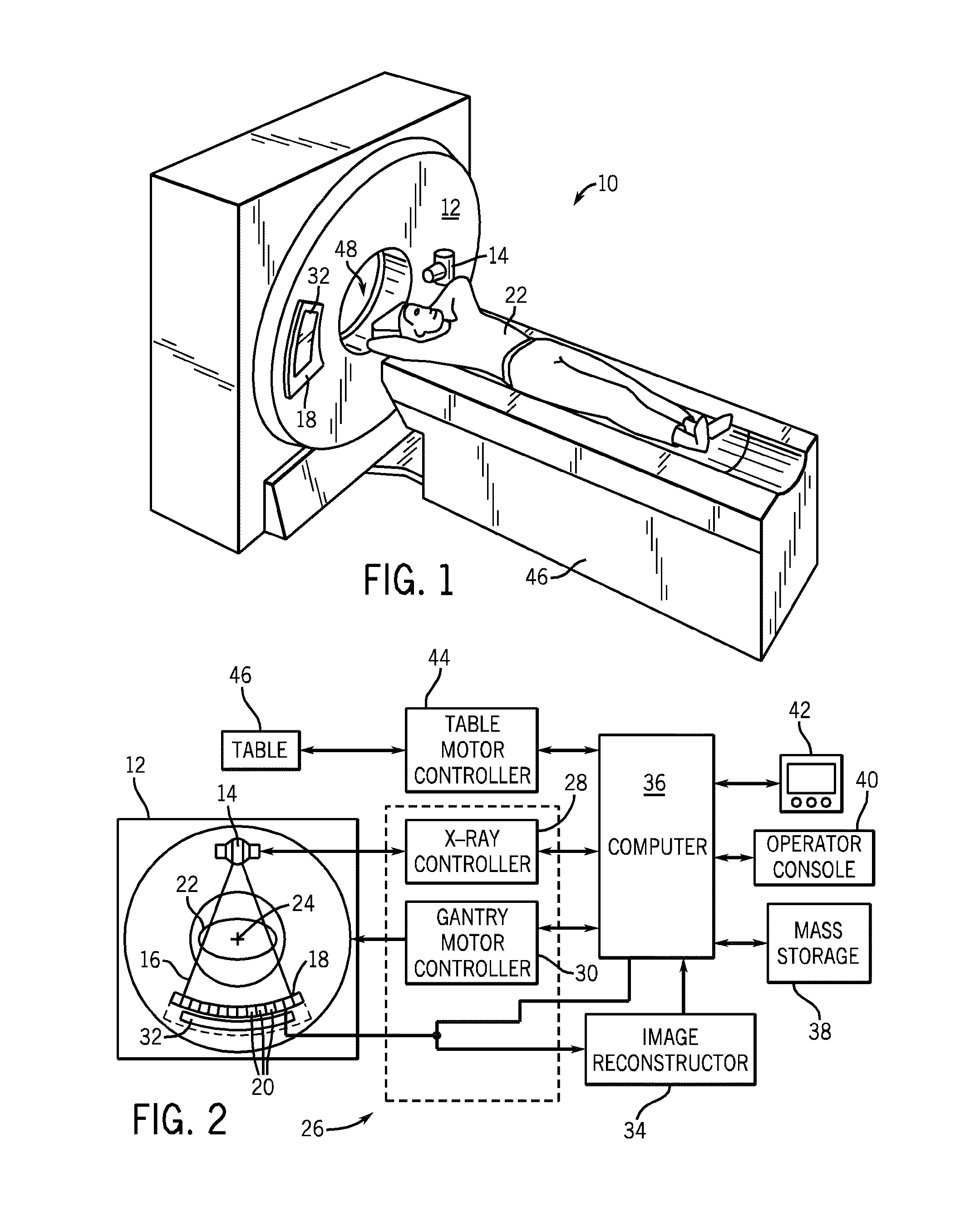
[0024]The operating environment of embodiments of the present invention is described with respect to a sixty-four-slice computed tomography (CT) system. However, it will be appreciated by those skilled in the art that the present invention is equally applicable for use with other multi-slice configurations. Moreover, the present invention will be described with respect to the detection and conversion of x-rays. However, one skilled in the art will further appreciate that the present invention is equally applicable for the detection and conversion of other high frequency electromagnetic energy. The present invention will be described with respect to a “third generation” CT scanner, but is equally applicable with other CT systems.

[0025]Referring to FIG. 1, a computed tomography (CT) imaging system 10 is shown as including a gantry 12 representative of a “third generation” CT scanner. Gantry 12 has an x-ray source 14 that projects a beam of x-rays 16 toward a detector assembly or colli...


PUM


Abstract

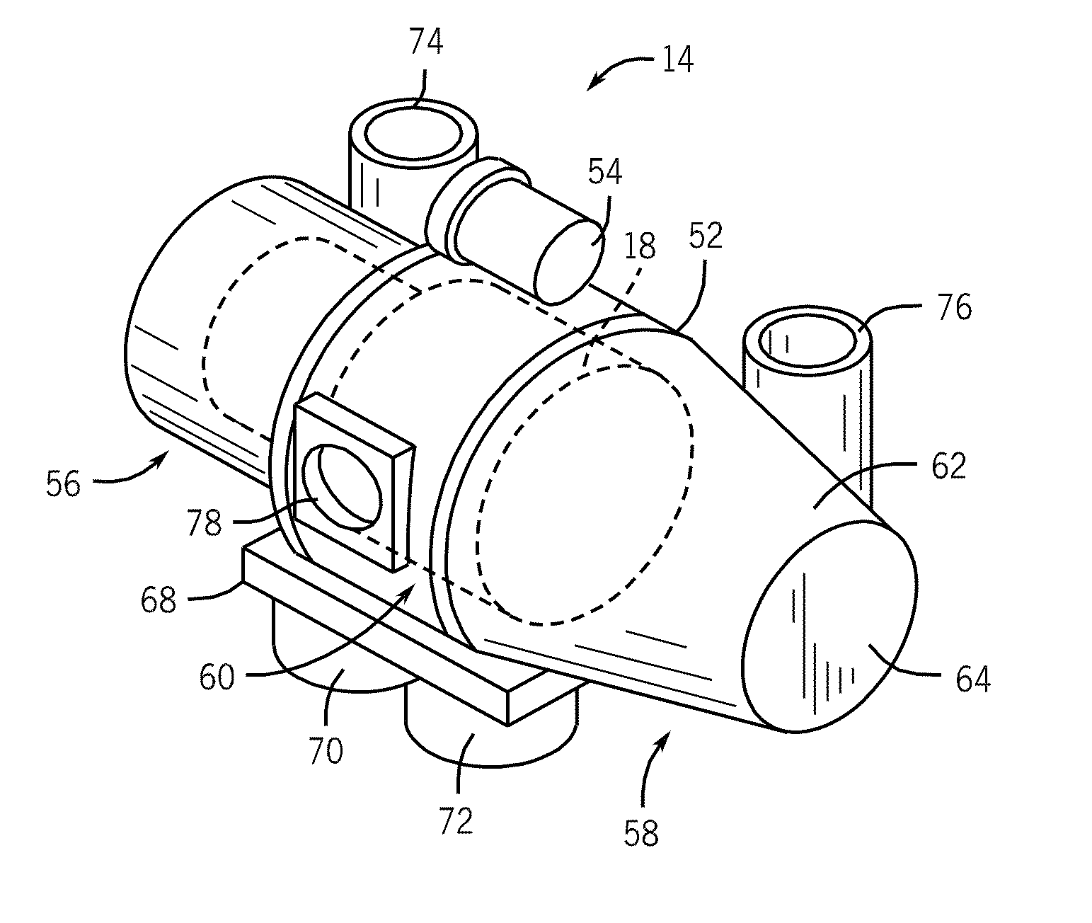
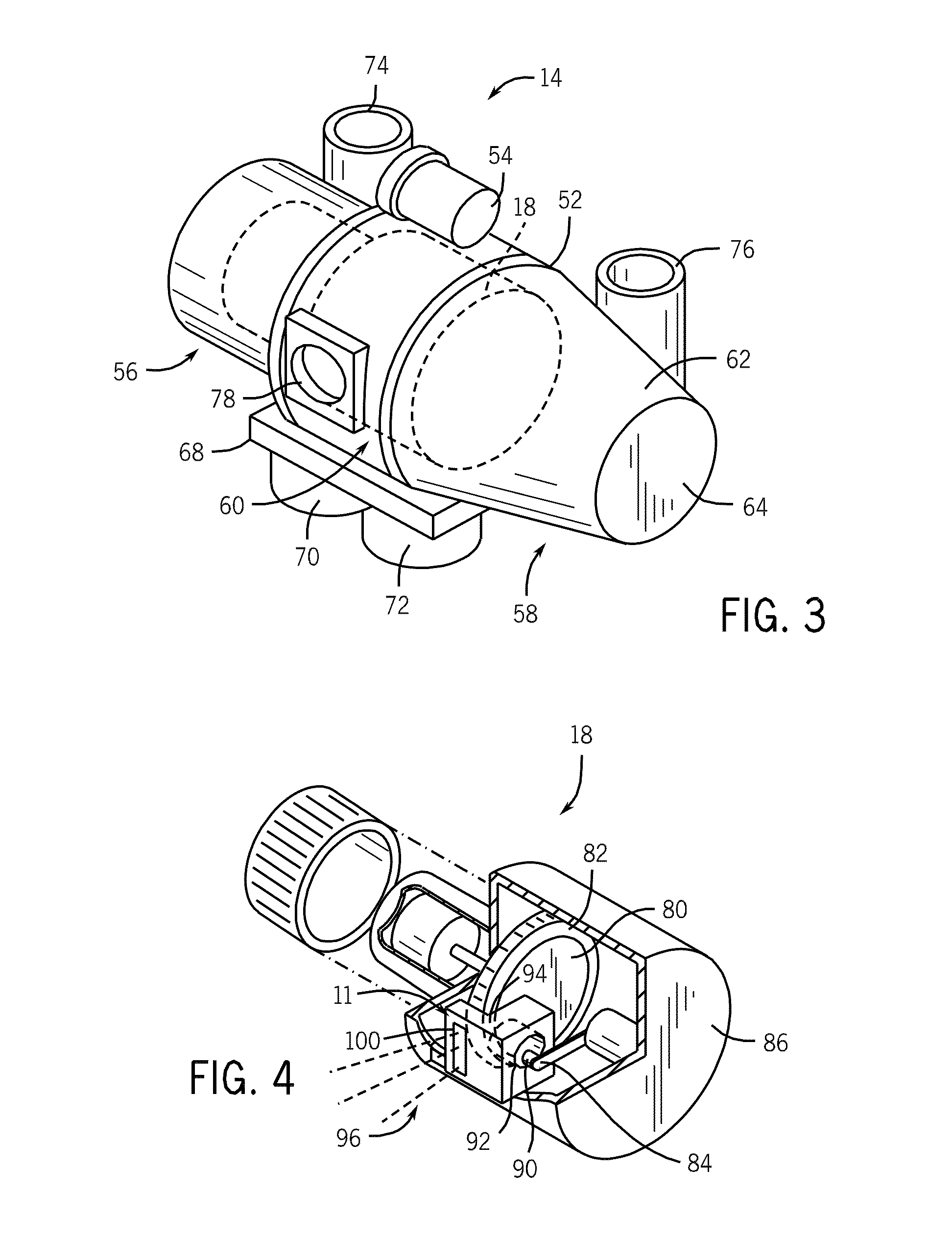
An apparatus includes an electron collector includes a body having an internal bore formed therethrough along a first direction and a window side having an aperture formed in a first portion thereof along a second direction different from the first direction. The apparatus also includes a cover plate having a bottom surface coupled to a second portion of the first surface of the electron collector, and an x-ray transmission window coupled to the cover plate and aligned with the aperture along the second direction, wherein a recess is formed along the second direction in one of the first portion of the first surface of the electron collector and a portion of the bottom surface of the cover plate, and wherein a gap is formed between the bottom surface of the cover plate and the first surface of the electron collector.

Description

BACKGROUND OF THE INVENTION[0001]Embodiments of the invention relate generally to a thermal management system, and more particularly, to a thermal energy storage and transfer assembly for gathering and dispersing radiant thermal energy and kinetic energy of electrons, such as within an electron beam generating device.[0002]Electron beam generating devices, such as x-ray tubes and electron beam welders, operate in a high temperature environment. Typically, an x-ray beam generating device or x-ray tube comprises opposed electrodes, a cathode and an anode, enclosed within a cylindrical vacuum vessel. A hot cathode filament emits thermal electrons that are accelerated across a typical voltage difference of 20 kV to 200 kV and impact the target zone of the anode at high velocity. The primary electron beam generated by the cathode deposits a very large heat load in the anode target to the extent that the target glows red-hot in operation. The x-rays are emitted in all directions, emanatin...

Claims


Application Information

Patent Timeline
Patent Type & Authority Applications(United States)
IPC IPC(8): H01J35/18H01J9/00
CPCH01J35/16H01J2235/1216H01J2235/122H01J2235/168H01J2235/18
Inventor HEBERT, MICHAEL SCOTTSTEINLAGE, GREGORY ALANSUBRAYA, MADHUSUDHANA T.ALLEN, DONALD ROBERTVAN BOGART, JAMES J.
Owner GENERAL ELECTRIC CO
Learn More