
Magnification control for lithographic imaging system

Active Publication Date: 2011-05-26
CORNING INC
View PDF9 Cites 13 Cited by
  • Summary
  • Abstract
  • Description
  • Claims
  • Application Information

AI Technical Summary

Benefits of technology

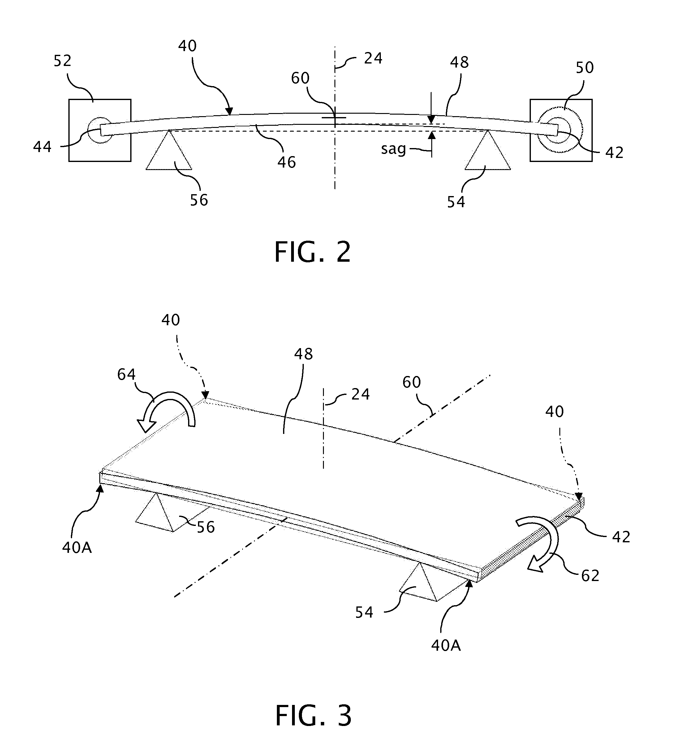
Preferably, the deformable plate is preloaded for imparting an initial amount of curvature to the deformable plate for contributing a limited amount of magnification power to the projection system. In one or more of its various forms, the invention (a) provides independent control over magnification in two orthogonal directions, (b) has minimal impact on aberrations of imaging systems, (c) requires relatively simple mechanics for operation, (d) allows for precisely matching optical imaging systems from one lithographic tool to another, and (e) allows for precisely matching multiple optical systems within a single lithographic tool.

Problems solved by technology

Illumination and projection systems combined under conditions of partial coherence further complicate the angular distribution of rays in object space required to maintain telecentricity in the image space.
As a result, the component shifts within object space can, in addition to changing magnification, also distort the images projected into image space or produce wavefront aberrations.

Method used


Image

  • Magnification control for lithographic imaging system
  • Magnification control for lithographic imaging system
  • Magnification control for lithographic imaging system

Examples


Embodiment Construction

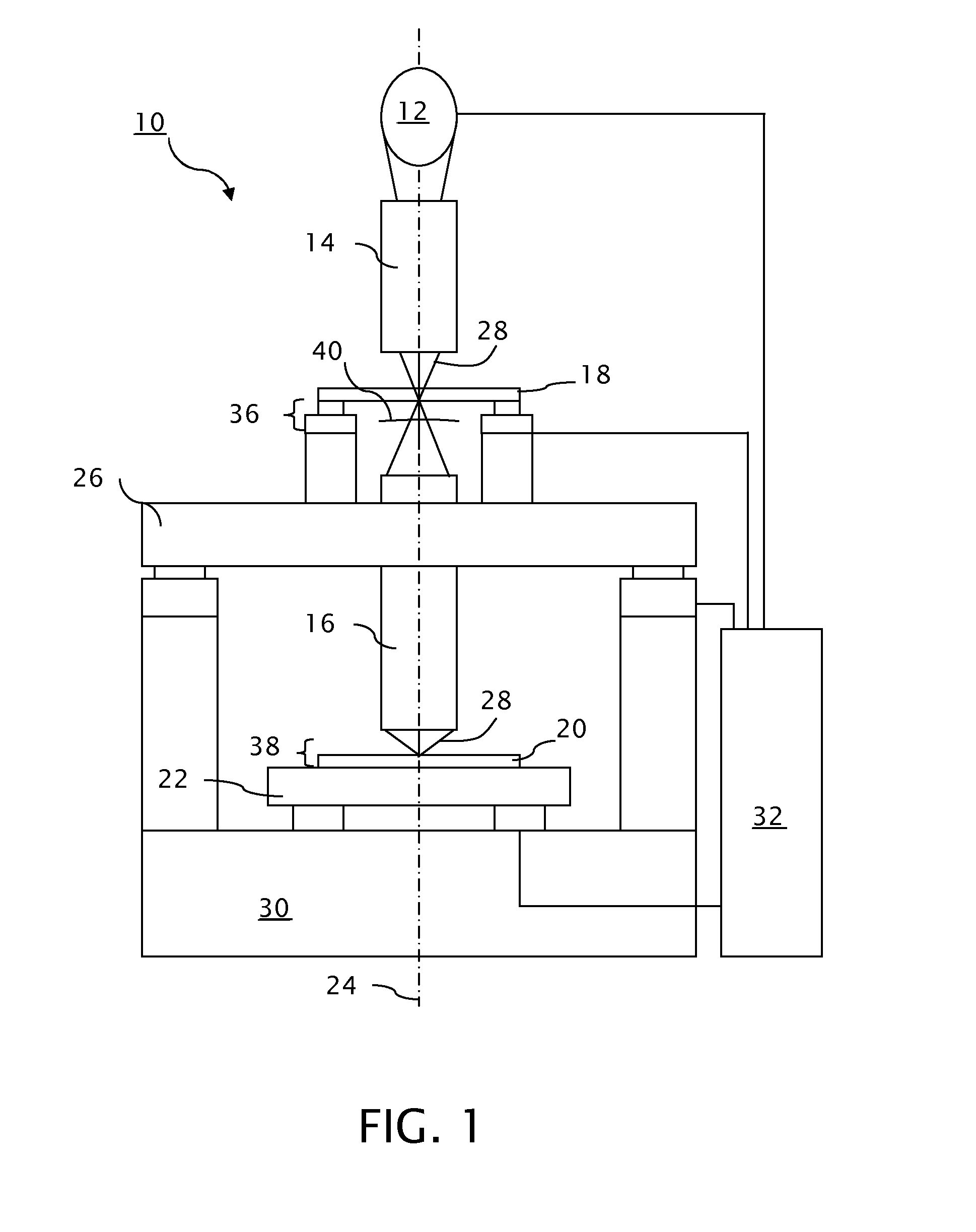
A microlithographic projection system (tool) 10, as an example of a projection system capable of benefitting from the invention, includes a light source 12, an illuminator 14, and a projection lens 16 for projecting an image of a reticle 18 onto a substrate 20. A horizontal X-Y-axis stage 22, which is translatable in two orthogonal directions normal to a common optical axis 24 of the illuminator 14 and the projection lens 16, provides for relatively moving the substrate 20 with respect to the projection lens 16 for exposing successive areas of the substrate 20. A vertical Z-axis stage 26 provides for relatively translating the projection lens 16 with respect to the substrate 20 along the optical axis 24 to provide for appropriately focusing the image of the reticle 18 onto the substrate 20.

The light source 12 emits radiation in the form of a beam of light 28 appropriate for developing the photosensitive substrate 20. A variety of known devices can be used to for the light source 12 ...


PUM


Abstract

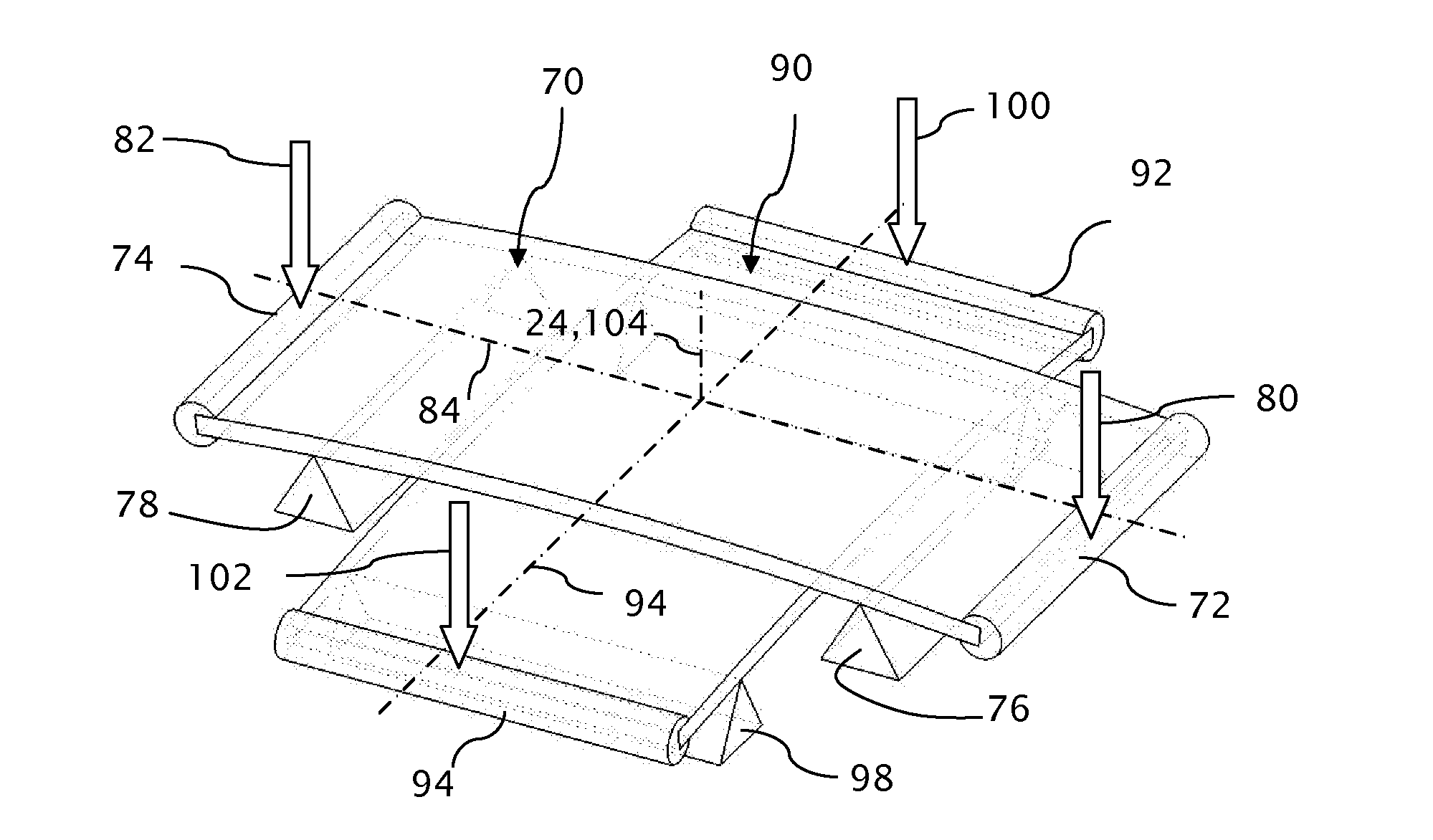
In a lithographic projection system, a corrective optic in the form of one or more deformable plates is mounted within telecentric image or object space for making one-dimensional or two-dimensional adjustments to magnification. The deformable plate, which can be initially bent under the influence of a preload, contributes weak magnification power that influences the magnification of the projection system by changing the effective focal length in object or image space. An actuator adjusts the amount of curvature through which the deformable plate is bent for regulating the amount of magnification imparted by the deformable plate.

Description

TECHNICAL FIELDThe invention concerns the lithographic projection of patterns onto substrates for such purposes as the manufacture of semiconductor devices or integrated circuits including flat panel displays and particularly concerns the management of the magnification of the projected patterns.BACKGROUND OF THE INVENTIONMicrolithographic projection systems project patterns onto substrates for selectively exposing photosensitive layers at multiple stages during the manufacture of microcircuits and microdevices. Often, the patterns must be stitched together to expose extended areas or registered with underlying patterns to build the desired circuits or devices. Image magnification of the projected patterns must be finely controlled to compensate for variations in operating conditions, such as changes in ambient temperature or pressure, to properly relate the patterns in successive exposures. Stepped lithography, which requires the stitching together of adjacent patterns, generally r...

Claims


Application Information

Patent Timeline
IPC IPC(8): G03B27/52G02B15/00G02B13/22
CPCG02B27/0025G03F7/70266G02B15/00G02B27/0043G03F7/70308
Inventor GREJDA, ROBERT D.MICHALOSKI, PAUL FRANCIS
Owner CORNING INC
Learn More