
On-window solar-cell heat-spreader

a solar cell and window heat-spreader technology, applied in the field of light concentration and illumination, can solve the problems of structural vulnerability, unbalanced appearance, and difficult heat removal of the rear location, and achieve the effect of easy cleaning and easy isolation from humidity

Inactive Publication Date: 2011-05-26
LIGHT PRESCRIPTIONS INNOVATORS
View PDF10 Cites 25 Cited by
  • Summary
  • Abstract
  • Description
  • Claims
  • Application Information

AI Technical Summary

Benefits of technology

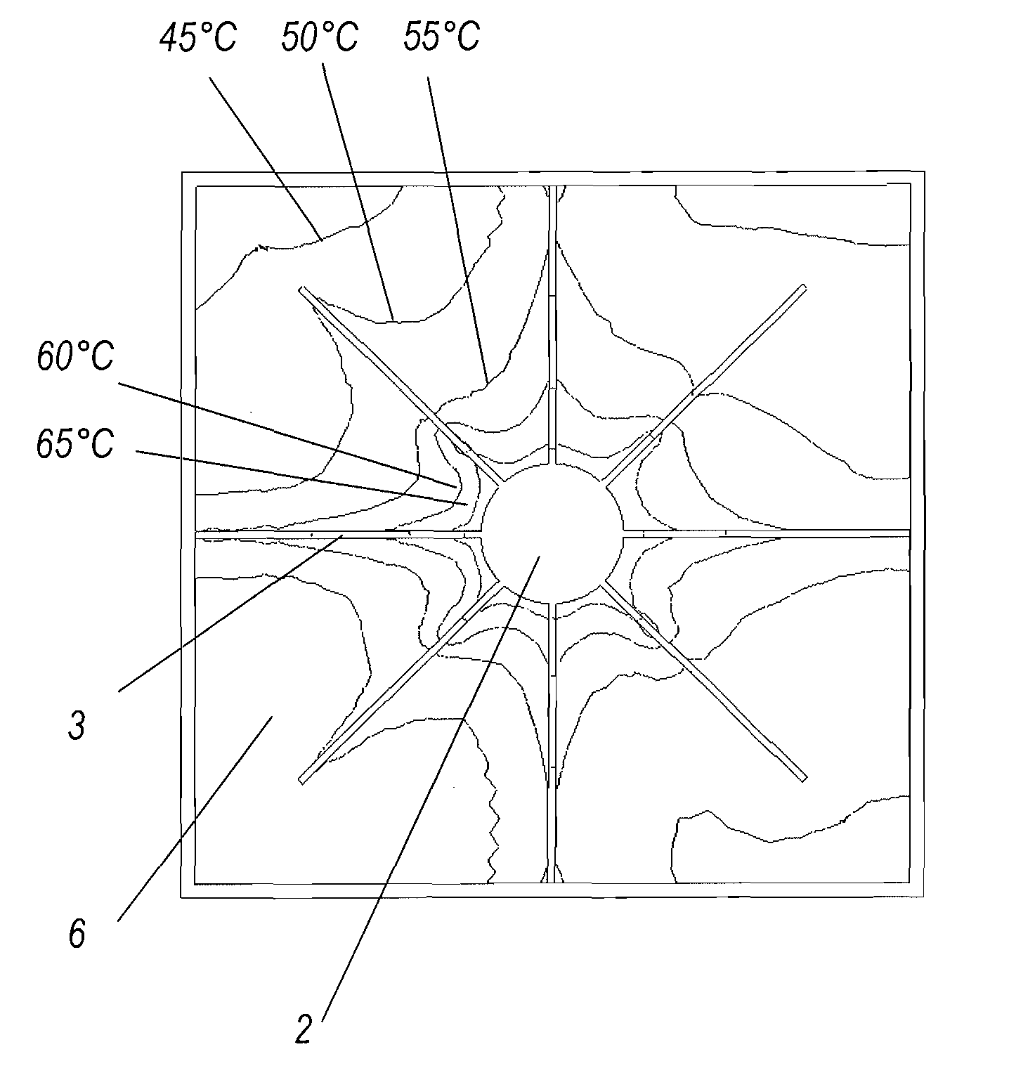
[0014]The present embodiments comprise a special transparent cover across the aperture of a reflective concentrator or collimator, further comprising provision for spreading the heat of the optoelectronic device across the inside of the cover. Once spread, the heat can easily flow through the cover's thickness to the ambient with a reasonable temperature drop even though glass and other commonly used cover materials have relatively low thermal conductivity. This is so because the heat flow area as been increased enough that the cover exhibits a low thermal resistance to the heat flow. A 6 mm thickness of glass will conduct 166 Watts / m2 when there is a 1° C. temperature difference from one face to the other of the glass, if the heat is flowing directly through the glass. Thus the 65% heat generation of a high-efficiency solar cell will require a 4° C. difference at one sun (1000 Watts / m2), which is a very small temperature drop.
[0026]The approach of the present embodiments is counter-intuitive in that it utilizes a material that is conventionally looked upon as an insulator, namely glass. Since reflector materials are vulnerable to dust and rain, a cover glass becomes the norm, even in embodiments that do not have a refracting element at the wide aperture, with the additional advantage of a flat surface being much easier to clean than a reflector dish. A sealed cover enables a controlled interior air volume to be established, so that the cell can more easily be isolated from humidity.

Problems solved by technology

In the latter situation, which obtains when the cell is at the prime focus of a reflector, heat removal is more difficult than for a rear location.
In this case, however, substantial heat dissipation can then be obtained only if the heat sink is impractically tall and skinny.
Such a configuration would be structurally vulnerable and aesthetically unbalanced.
Although the thermal performance of this XR system is quite good, the heat sink has disadvantages, including its large size, high cost, and difficulty of sealing.

Method used


Image

  • On-window solar-cell heat-spreader
  • On-window solar-cell heat-spreader
  • On-window solar-cell heat-spreader

Examples


Embodiment Construction

[0051]A better understanding of various features and advantages of the present invention will be obtained by reference to the following detailed description of embodiments the invention and accompanying drawings, which set forth illustrative embodiments that utilize particular principles of the invention.

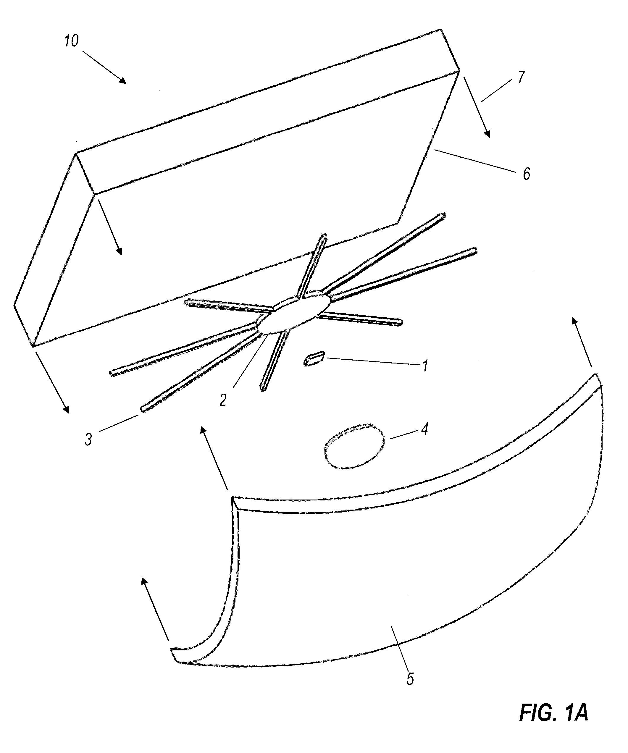
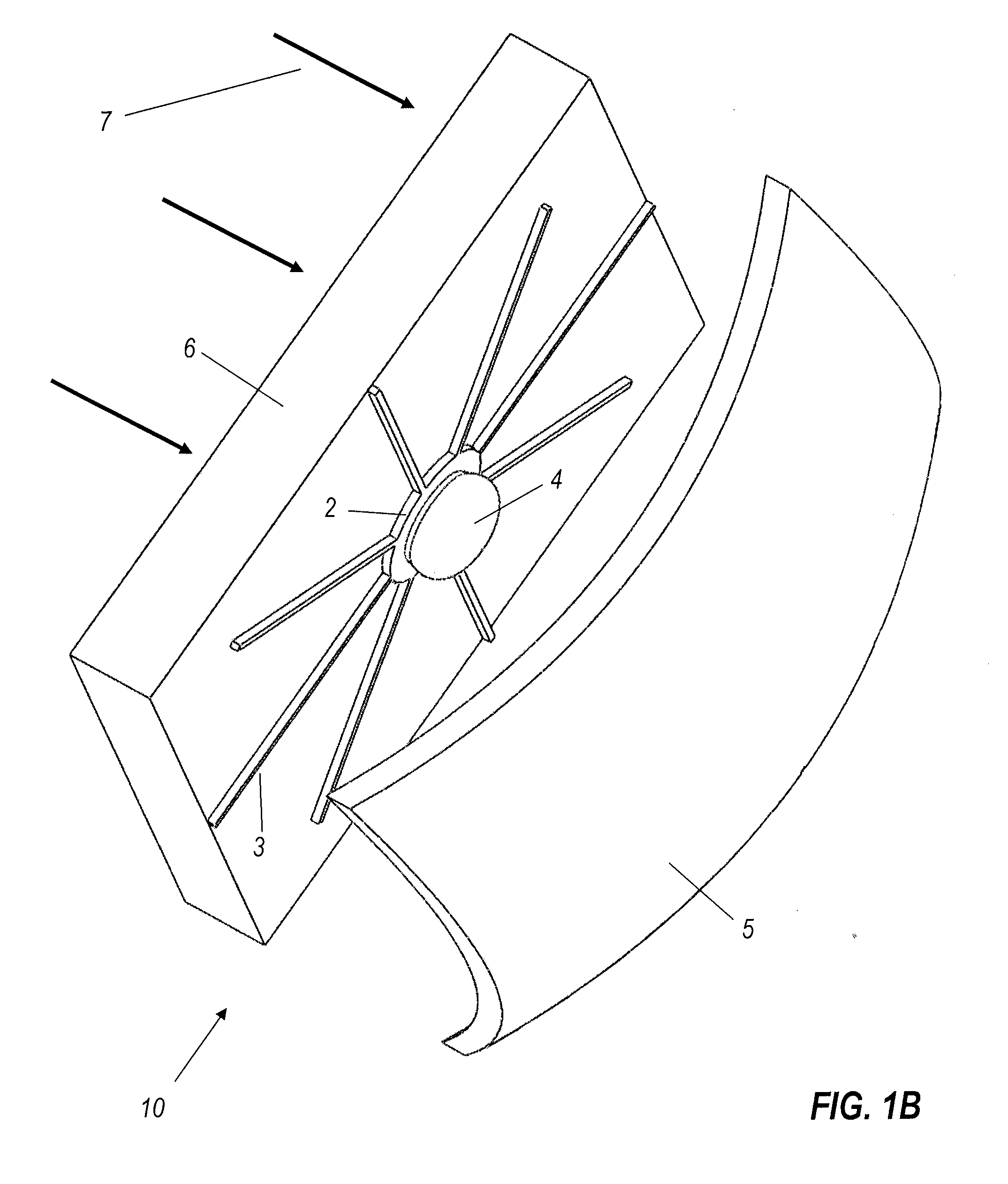
[0052]Referring initially to FIGS. 1A through 1D (collectively FIG. 1), FIG. 1A is an exploded view, and FIG. 1B an assembled view, of a first embodiment of a solar concentrator 10, comprising photovoltaic (PV) chip 1 mounted on a base 2, spreader bars or strips 3 radially extending from base 2, and secondary lens 4 covering PV chip 1. Base 2, with spreader bars 3, PV chip 1, and secondary lens 4, is mounted on the inside of cover glass 6, which is faced by primary reflector 5. In an example, primary reflector 5 is 50 mm on a side, and secondary lens 4 is 10 mm in diameter. Primary reflector 5 receives incoming direct solar rays 7 through cover glass 6, and concentrates the rays upo...


PUM


Abstract

An optoelectrical device, which may be a luminaire or a photovoltaic concentrator, has a transparent cover plate. A target with an optoelectrical transducer that produces waste heat in operation is mounted at an inside face of the transparent cover plate. A primary mirror reflects light between being concentrated on the target and passing generally collimated through the cover plate. A heat spreader is in thermal contact with the target. The heat spreader has heat conductors that thermally connect the target with the inside surface of the cover plate. The heat conductors may be arms extending radially outwards, and may be straight, zigzag, or branching. An array of targets may be mounted on a common cover plate, and their heat spreaders may be continuous from target to target.

Description

CROSS-REFERENCE TO RELATED APPLICATIONS[0001]This application claims benefit of U.S. Provisional Patent Application No. 61 / 264,328, filed Nov. 25, 2009 by Miñano et al., titled “On-window solar-cell heat spreader,” which is incorporated herein by reference in its entirety.[0002]This application is related to the following patents and patent applications by several of the same inventors, which are incorporated herein by reference in their entirety.[0003]U.S. Pat. No. 6,639,733 “High Efficiency Non-Imaging Optics.”[0004]U.S. Pat. No. 7,460,985 “Three-dimensional simultaneous multiple-surface method and free-form illumination-optics designed therefrom.”[0005]US 2008 / 0316761 “Free-Form Lenticular Optical Elements and Their Application to Condensers and Headlamps.”[0006]US 2009 / 0071467 “Multi-junction solar cells with a homogenizer system and coupled non-imaging light concentrator.”[0007]WO 2008 / 112310 “Optical concentrator, especially for solar photovoltaics.”[0008]WO 2009 / 099605 “Trans...

Claims


Application Information

Patent Timeline
Patent Type & Authority Applications(United States)
IPC IPC(8): H01L31/06H01J7/24G01J1/42H01L31/0232
CPCG01J1/02G01J1/0252G01J1/04G01J1/0411H01L31/0547H01L31/052Y02E10/52H01L31/0543G01J1/0422
Inventor MINANO, JUAN CARLOSBENITEZ, PABLOCHAVES, JULIO C.FALICOFF, WAQIDISUN, YUPIN
Owner LIGHT PRESCRIPTIONS INNOVATORS
Learn More