Eureka AIR delivers breakthrough ideas for toughest innovation challenges, trusted by R&D personnel around the world.

Battery assembly

Active Publication Date: 2011-05-05
ENERDEL
View PDF28 Cites 59 Cited by
  • Summary
  • Abstract
  • Description
  • Claims
  • Application Information

AI Technical Summary

Benefits of technology

[0013]Alluding to the above, FIG. 7 of the U.S. Pat. No. 6,821,671 to Hinton et al. shows the apparatus wherein straps are inserted through ears extending from the cooling fins to connect multiple battery cells to form the apparatus and fins together to keep the battery cells in compression. The straps, as shown in FIG. 7 deform the battery cells thereby negatively affecting chemical reaction between electrolyte, cathodes and anodes of each battery cells and resulting in a reduced life span of the cells.
[0028]The disclosed battery assembly provides several advantages over the battery packs of the prior art by increasing an ambient temperature range at which the battery pack can operate. Also, the disclosed battery assembly helps maintain the battery pack at an optimal operating temperature to extend the life cycle of the battery pack, and to increase battery pack safety.

Problems solved by technology

Due to the characteristics of the lithium ion batteries, the battery pack operates within an ambient temperature range of −20° C. to 60° C. However, even when operating within this temperature range, the battery pack may begin to lose its capacity or ability to charge or discharge should the ambient temperature fall below 0° C. Depending on the ambient temperature, the life cycle capacity or charge / discharge capability of the battery may be greatly reduced as the temperature strays from 0° C. Nonetheless, it may be unavoidable that the lithium ion battery be used where the ambient temperature falls outside the ambient temperature range.
Alluding to the above, in a battery or battery assembly with multiple cells, significant temperature variances can occur from one cell to the next, which is detrimental to performance of the battery pack.
This will lead to decline in the performance of the entire pack.
Thus the U.S. Pat. No. 5,071,652 to Jones et al. does not teach creating a clearance between the vessel and the heat transfer members, which can be used to introduce cooling or heating agent to cool or heat the cells.
If, for example, the cooling agent is applied to the front of the apparatus, only first battery cell is exposed to the cooling agent thereby preventing effective cooling of other battery cells.
The straps, as shown in FIG. 7 deform the battery cells thereby negatively affecting chemical reaction between electrolyte, cathodes and anodes of each battery cells and resulting in a reduced life span of the cells.
However, the metallic cases are expensive to manufacture and each different configuration requires new dies to produce the various components and new tools to assemble those components.
Unfortunately, these packages do not provide structural rigidity or protection from handling and vibration nearly as well as the metallic cases, nor can they be combined into consistently sized groups of cells because of the inherent variation in the thickness of a lithium battery cell pack.
The potting material also prevents the cell packaging from relaxing over time and allowing the electrolyte to settle into the base of the cell package and thus reducing the cell's electrical capacity.

Method used


Image

  • Battery assembly
  • Battery assembly
  • Battery assembly

Examples


Embodiment Construction

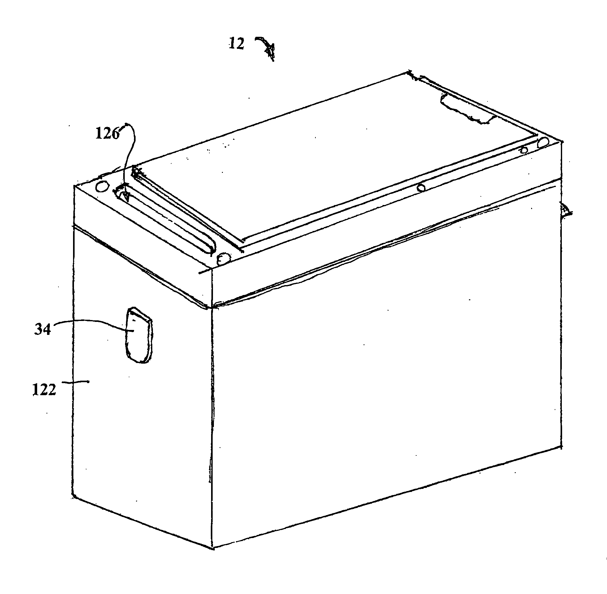
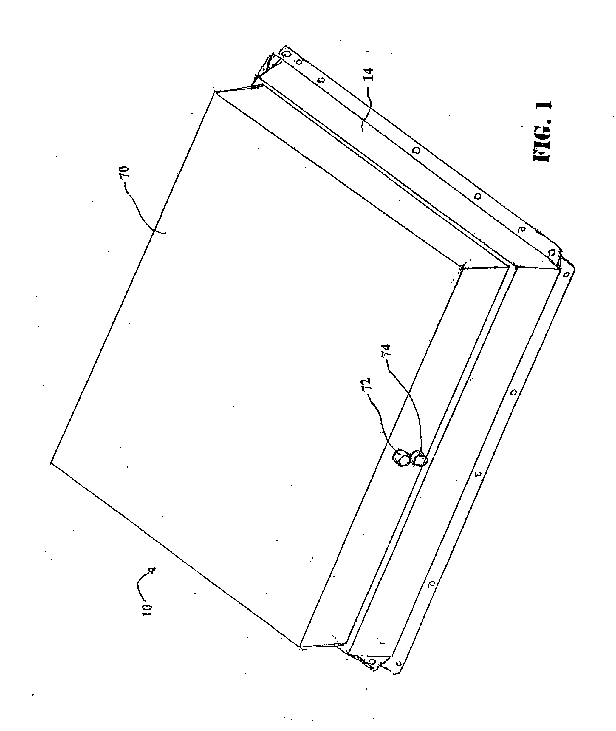
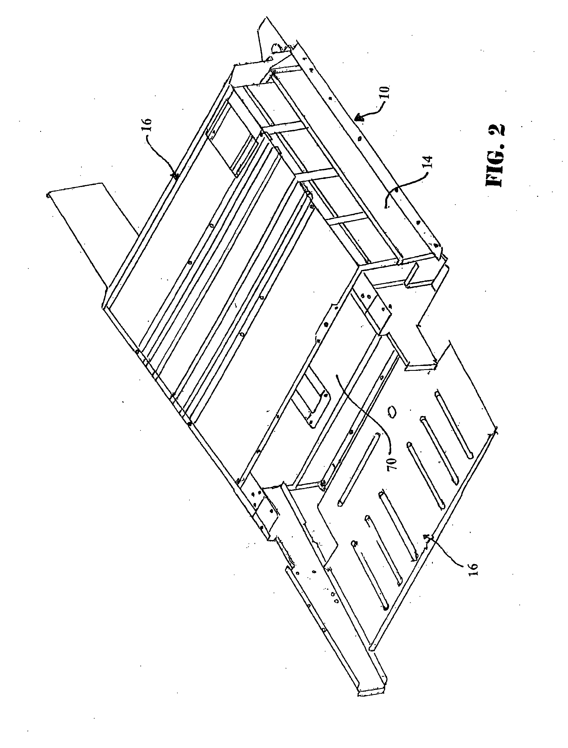
[0058]Referring to the Figures, wherein like numerals indicate like or corresponding parts, a battery assembly or battery pack of the present disclosure is adaptable to be utilized in various configurations including and not limited to a horizontally or vertically stacked battery cell packaging configuration used in an automotive vehicle applications. The battery assembly or pack or battery pack assembly is generally shown at 10 in FIG. 1. The battery assembly 10 includes a plurality of battery sub-packs, each generally shown at 12 in FIG. 1.

[0059]As best shown with reference to FIGS. 11-22, each battery module 13 of each sub-pack 12 includes a plurality of cells 91. Preferably, each cell 91 is a lithium ion cell without limiting the scope of the present disclosure. Those skilled in the battery art will appreciate that other cells can be utilized within the scope of the present disclosure. Each cell 91 includes a plurality of battery components (not shown) co-acting between one anot...


PUM


Abstract

A battery module includes pressure release features (37, 38) for releasing excess pressure in a battery container, a wrap blanket (150) disposed between a module (13) and potting material (152) disposed in a case to secure modules (13) while allowing repair, replacement, recycling and / or reuse of modules (13) and a connector (130).

Description

FIELD OF THE INVENTION[0001]The subject disclosure relates to battery packs having cells and more particularly, to a battery pack for vehicles having a cooling system or a heating system for cooling the cells within the battery pack.BACKGROUND AND SUMMARY[0002]Motor vehicles, such as, for example, hybrid vehicles and electric vehicles use propulsion systems to provide motive power. In hybrid vehicles, the propulsion system most commonly refers to gasoline-electric hybrid vehicles, which use gasoline (petrol) to power internal-combustion engines (ICEs), and electric batteries to power electric motors. These hybrid vehicles recharge their batteries by capturing kinetic energy via regenerative braking. When cruising or idling, some of the output of the combustion engine is fed to a generator (merely the electric motor(s) running in generator mode), which produces electricity to charge the batteries. This contrasts with all-electric cars which use batteries charged by an external source...

Claims


Application Information

Patent Timeline
IPC IPC(8): H01M2/12H01M2/30H01M10/50
CPCF16K17/16H01M10/5095H01M2/0245H01M2/1229H01M2/1241H01M6/42H01M10/5004H01M10/5006H01M10/5016H01M10/5032H01M10/5046H01M10/5055H01M10/5059H01M10/5061H01M2/0217H01M10/625H01M10/615H01M10/663H01M10/647H01M10/6551H01M10/6557H01M10/6555H01M10/613H01M10/656Y02E60/10H01M50/258H01M50/103H01M50/325H01M50/3425H01M50/30
Inventor BUCK, DERRICK S.FATTIG, ROBERT N.SILK, BRUCE J.
Owner ENERDEL
Why Eureka
Eureka Blog
Learn More