
Method and apparatus for temperature, conductance and/or impedance testing in remote application of battery monitoring systems

Inactive Publication Date: 2007-03-01
ENERSAFE
View PDF11 Cites 111 Cited by
  • Summary
  • Abstract
  • Description
  • Claims
  • Application Information

AI Technical Summary

Benefits of technology

[0006] An exemplary battery monitoring system may be provided, which measures various parameters for a single or multiple batteries, and includes a data processing and / or storage unit which may be configured to be local and / or remote to the battery via a wireless connection or a combination of a wireless and wired connection. In this regard, the absence of, or at least reduction, in the number of wired connections between the battery and the data processing and / or storage unit, or between the data processing and / or storage unit and other remote applications, may provide improved installation, maintenance, and reliability of the monitoring system and / or the battery. In particular, the use of wireless communications and remote devices may provide improved management and monitoring capabilities at reduced cost.

Problems solved by technology

There may be a cost associated with monitoring a battery, in which the size of the investment is defined by the range of monitored parameters, which in turn may be weighed against the end user's willingness to pay for monitoring information.
Conductance, for example, is one of the most often recommended indicators of the battery State of Health (SOH), yet it may be one of the most difficult to test in remote applications.
For example, it is believed there is no simple and inexpensive device which allows users to perform these types of test in remote locations without actually traveling to the site.
In particular, there is no on-line, yet inexpensive equipment on the market for small, remote battery systems such as CEV, Outside Plant or Customer Premises Telecommunications applications.

Method used


Image

  • Method and apparatus for temperature, conductance and/or impedance testing in remote application of battery monitoring systems
  • Method and apparatus for temperature, conductance and/or impedance testing in remote application of battery monitoring systems
  • Method and apparatus for temperature, conductance and/or impedance testing in remote application of battery monitoring systems

Examples


Embodiment Construction

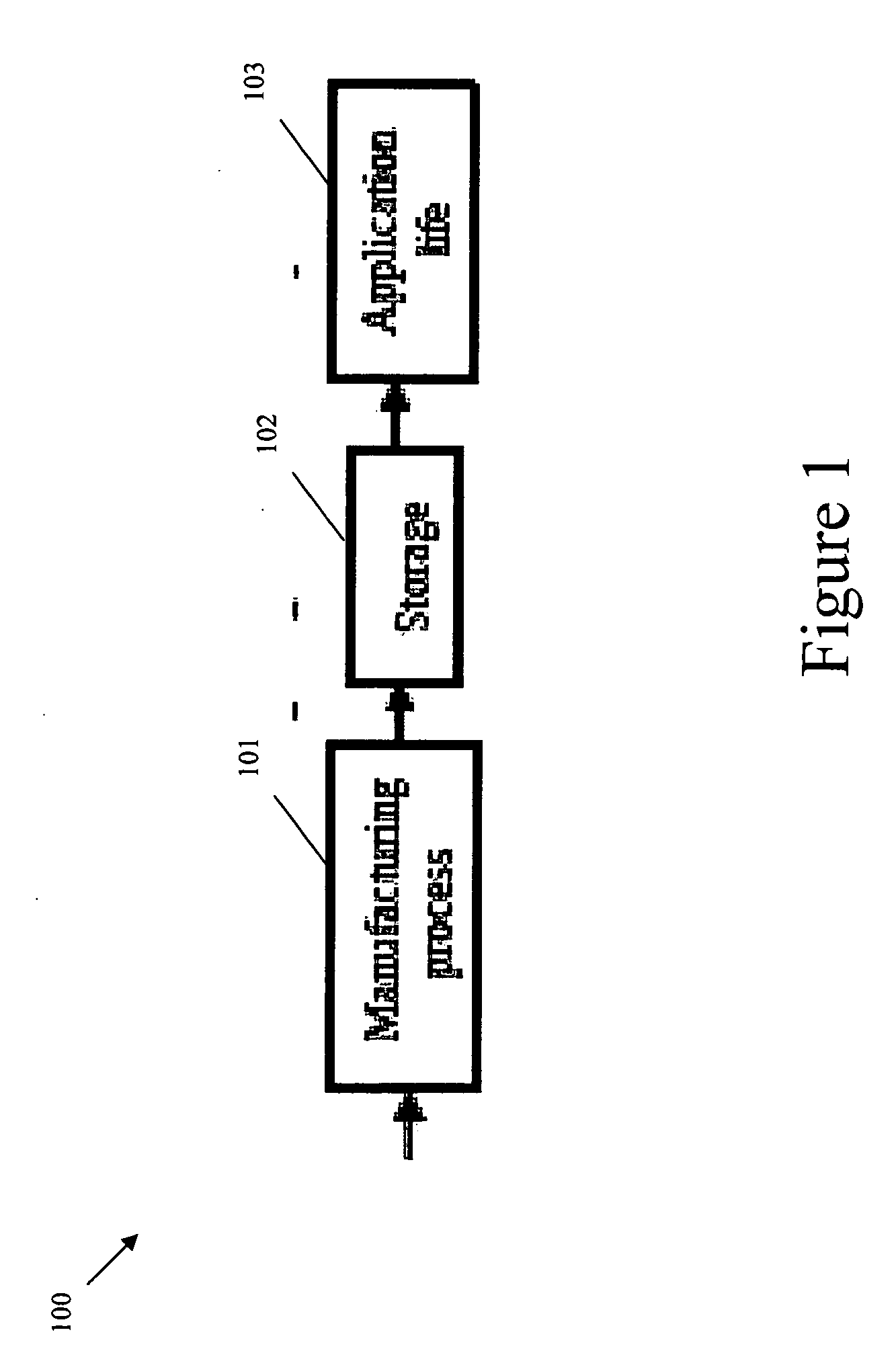
[0054]FIG. 1 shows exemplary battery life cycle 100, which includes a manufacturing phase 101, a post shipment storage phase 102 and an application life phase 103. The manufacturing phase 101 includes the period from the time that the battery is first charged through the time it is stored in the factory. The post shipment storage phase 102 includes the period from the time the battery is shipped from the factory until the time the battery is installed into service. The application life phase 103 includes the period from the time the battery is commissioned into service until it is removed and scrapped. Each of the life cycle phases may involve a different set of features to be monitored and recorded.

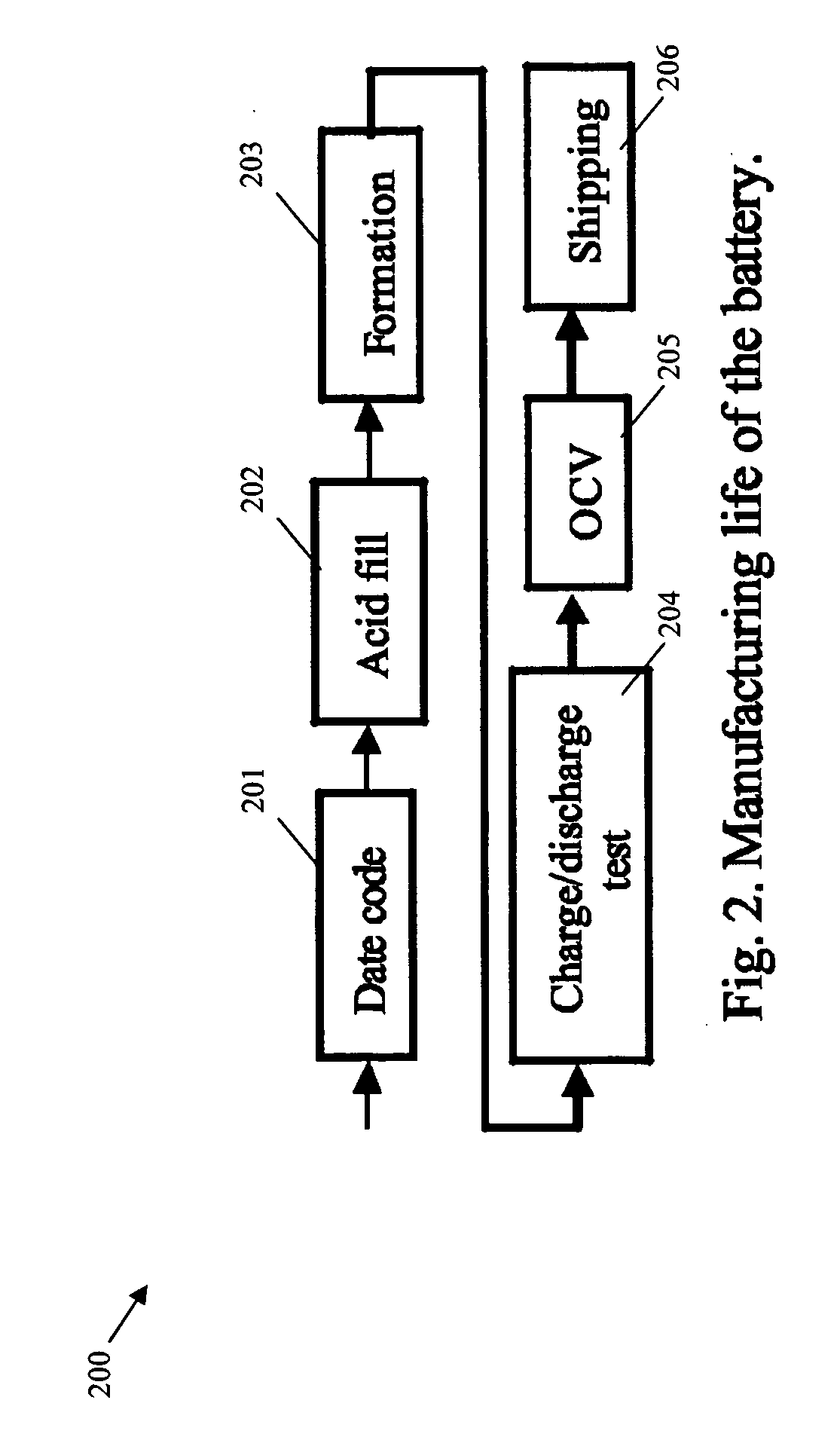
[0055]FIG. 2 shows a block diagram representing exemplary stages 201-206 of the manufacturing process phase 101 of FIG. 1 for operations involving electrical measurements. The exemplary stages include a date code assignment stage 201, an acid fill stage 202, a formation stage 203, a cha...


PUM


Abstract

An apparatus and method of monitoring at least one battery, includes measuring an analog signal related to the at least one battery, converting the analog signal to a digital signal and communicating the digital signal in a wireless manner to an external device, in which the measuring, converting, and communicating are performed by an arrangement that is embedded in or attached to the at least one battery.

Description

CROSS-REFERENCE TO RELATED APPLICATION [0001] The present application claims the benefit of U.S. Provisional Patent Application Ser. No. 60 / 709,183, filed on Aug. 17, 2005, which is expressly incorporated herein in its entirety by reference thereto.FIELD OF THE INVENTION [0002] The present invention relates to battery monitoring systems, in particular, a method and apparatus for temperature, conductance, and / or impedance testing in remote application of battery monitoring systems. BACKGROUND INFORMATION [0003] There may be a cost associated with monitoring a battery, in which the size of the investment is defined by the range of monitored parameters, which in turn may be weighed against the end user's willingness to pay for monitoring information. This willingness to pay may be a function of lost revenue exposure, cost savings, or health and safety issues that may be directly attributable to the failure of a DC backup system. For example, the batteries that power building management...

Claims


Application Information

Patent Timeline
IPC IPC(8): H02J7/00
CPCG01R31/3641G01R31/3648G01R31/3675G01R31/3662G01R31/3658G01R31/396G01R31/3865G01R31/389G01R31/374
Inventor POREBSKI, WOJCIECH
Owner ENERSAFE
Learn More