Polarization element, liquid crystal device, electronic device, and method of manufacturing polarization element
a technology of polarizing elements and liquid crystal devices, which is applied in the direction of polarizing elements, optical elements, instruments, etc., can solve the problems of reducing the surface area of the polarizing element, reducing the number of components, and deteriorating the polarizing element, so as to achieve the effect of increasing the surface area
- Summary
- Abstract
- Description
- Claims
- Application Information
AI Technical Summary
Benefits of technology
Problems solved by technology
Method used
Image


Examples
first embodiment
Configuration of Polarization Element
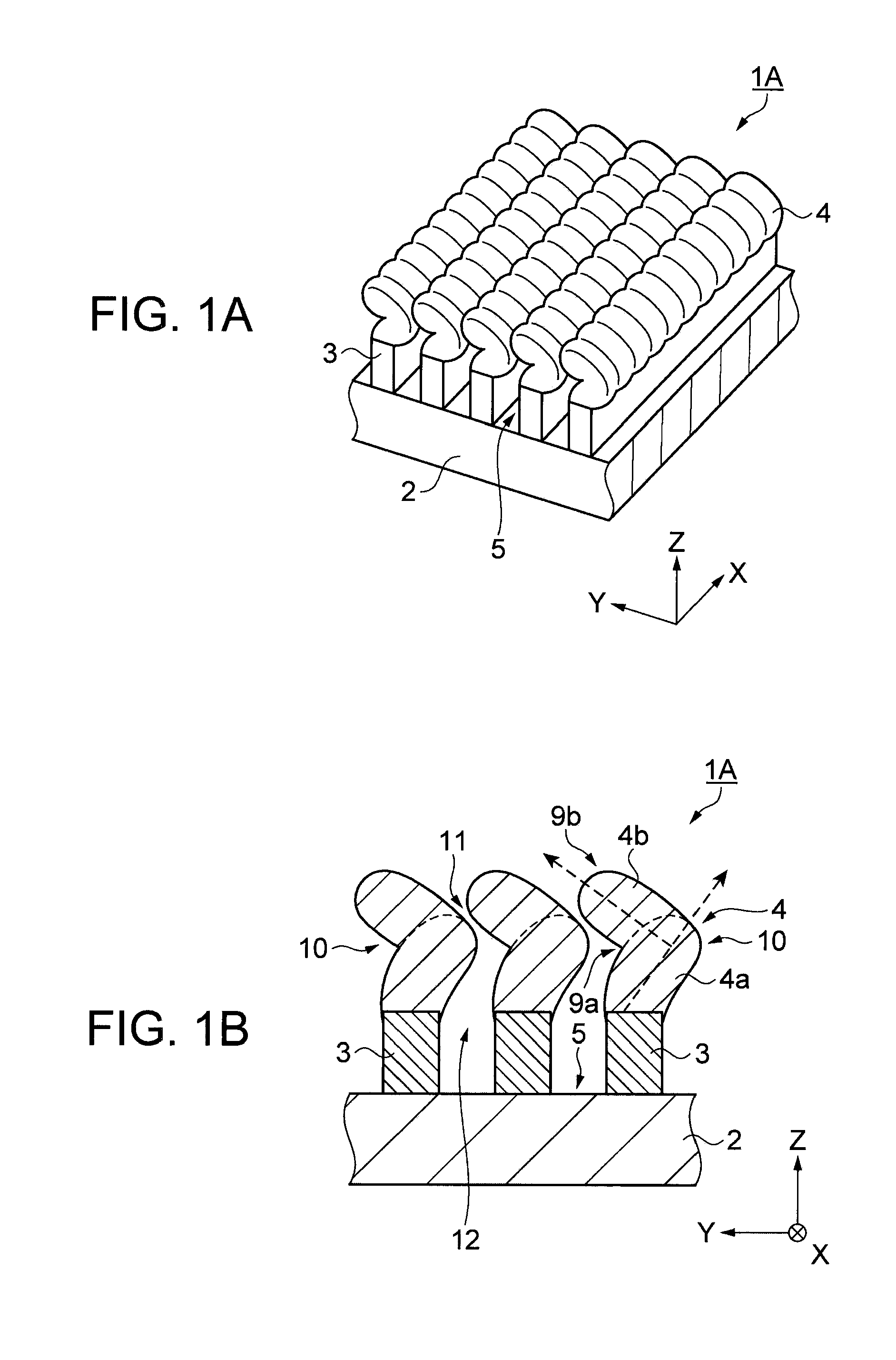
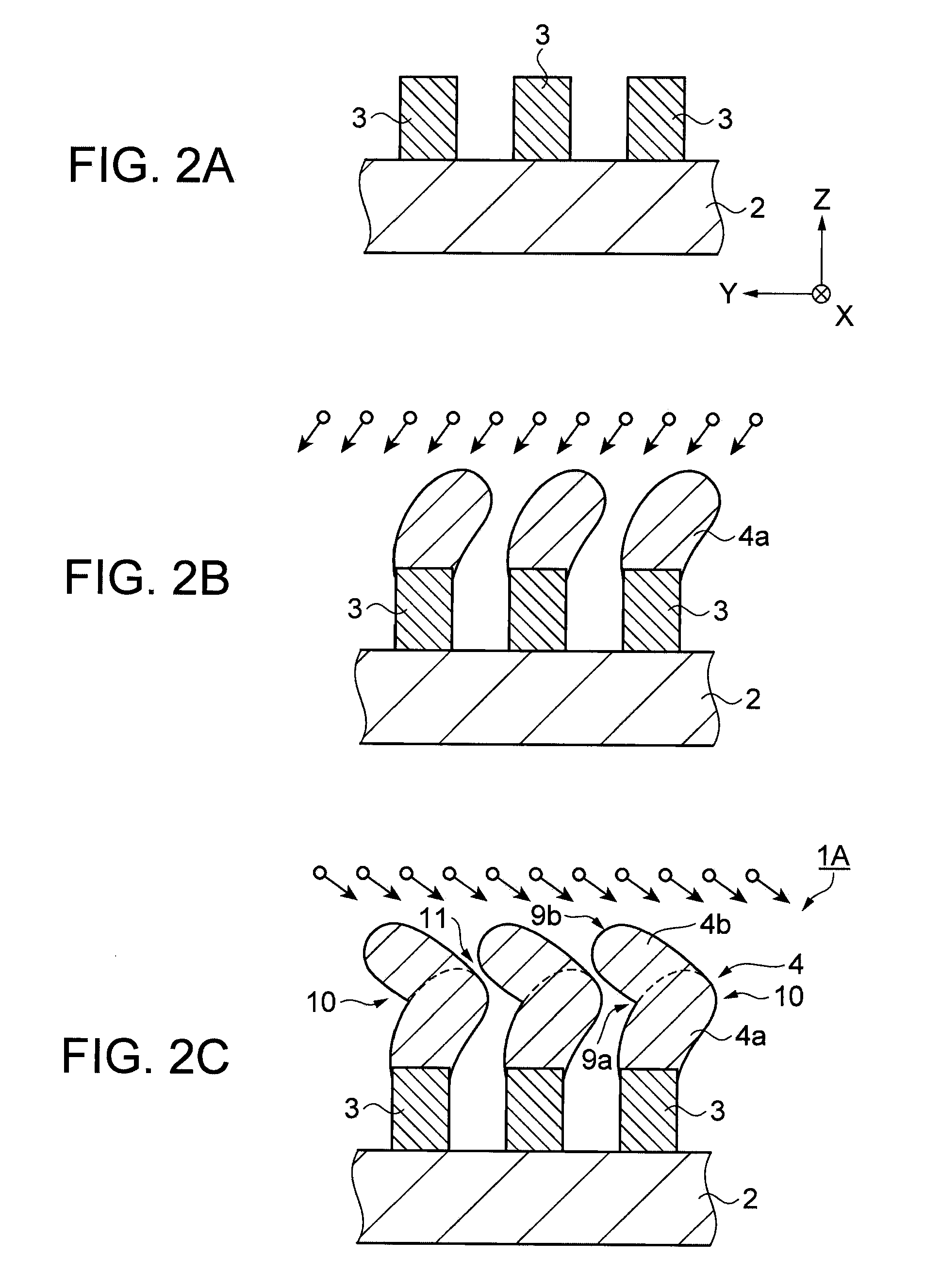
[0055]Firstly, a configuration of the polarization element will be explained. FIGS. 1A and 1B show the configuration of the polarization element according to a first embodiment of the invention, wherein FIG. 1A is a perspective view, and FIG. 1B is a cross-sectional view. It should be noted that in the following explanations, an XYZ coordinate system is assumed, and positional relationships between the respective members will be explained with reference to the XYZ coordinate system. In this case, it is assumed that a predetermined direction in a horizontal plane is an X-axis direction (a first direction), a direction perpendicular to the X-axis direction in the horizontal plane is a Y-axis direction (a second direction), a direction perpendicular to both of the X-axis direction and the Y-axis direction in a vertical plane is a Z-axis direction. In the illustrations of the present embodiment, it is assumed that the direction along which protruding...
second embodiment
[0097]A second embodiment will hereinafter be described.
Configuration of Polarization Element
[0098]Firstly, a configuration of the polarization element will be explained. FIG. 6 is a schematic diagram of the polarization element according to the second embodiment. The polarization element 1B according to the present embodiment is different from the polarization element 1A according to the first embodiment in that there are provided third heat radiation sections 4c. Since the other points are substantially the same as those of the first embodiment, the same sections are denoted as the same reference symbols. Further, in the following explanation, an XYZ coordinate system is assumed, and positional relationships between the respective members will be explained with reference to the XYZ coordinate system. In this case, it is assumed that a predetermined direction in a horizontal plane is an X-axis direction, a direction perpendicular to the X-axis direction in the horizontal plane is a...
third embodiment
[0116]A third embodiment will hereinafter be described.
Configuration of Polarization Element
[0117]Firstly, a configuration of the polarization element will be explained. FIG. 8 is a cross-sectional view of the polarization element according to the third embodiment. The polarization element 1C according to the present embodiment is different from the first embodiment in the form of the protruding sections 3. Since the other points are substantially the same as those of the first embodiment, the same sections are denoted as the same reference symbols. Further, in the following explanation, an XYZ coordinate system is assumed, and positional relationships between the respective members will be explained with reference to the XYZ coordinate system. In this case, it is assumed that a predetermined direction in a horizontal plane is an X-axis direction, a direction perpendicular to the X-axis direction in the horizontal plane is a Y-axis direction, and a direction perpendicular to both of...
PUM
| Property | Measurement | Unit |
|---|---|---|
| width | aaaaa | aaaaa |
| width | aaaaa | aaaaa |
| width | aaaaa | aaaaa |
Abstract
Description
Claims
Application Information
 - R&D
- Intellectual Property
- Life Sciences
- Materials
- Tech Scout
- Unparalleled Data Quality
- Higher Quality Content
- 60% Fewer Hallucinations
Browse by: Latest US Patents, China's latest patents, Technical Efficacy Thesaurus, Application Domain, Technology Topic, Popular Technical Reports.
© 2025 PatSnap. All rights reserved.Legal|Privacy policy|Modern Slavery Act Transparency Statement|Sitemap|About US| Contact US: help@patsnap.com