Gas detector and process for monitoring the concentration of a gas

a gas detector and gas concentration technology, applied in the field of gas detectors, can solve the problems of high cost, complex ion mobility spectrometers (ims) and mass spectrometers (ms), and achieve the effects of high cost, high accuracy, and rapid processing

Inactive Publication Date: 2011-04-28
DRAGERWERK AG
View PDF4 Cites 5 Cited by
  • Summary
  • Abstract
  • Description
  • Claims
  • Application Information

AI Technical Summary

Benefits of technology

[0008]Based on this state of the art, the object of the present invention is therefore to provide a cost-effective, rapid but highly sensitive gas sensor especially for detecting analytes with high proton affinity in the lower ppb range.
[0016]To make it possible to select the ions according to the recombination time, the electron pulse of the electron source and the transfer field pulse are offset in time. For example, certain ions, whose recombination time is shorter than the distance in time between the electron pulse and the transfer field pulse, can be excluded from detection in this manner.

Problems solved by technology

Ion mobility spectrometers (IMS) and mass spectrometers (MS) are relatively complex and also very expensive.

Method used


Image

  • Gas detector and process for monitoring the concentration of a gas
  • Gas detector and process for monitoring the concentration of a gas
  • Gas detector and process for monitoring the concentration of a gas

Examples


Embodiment Construction

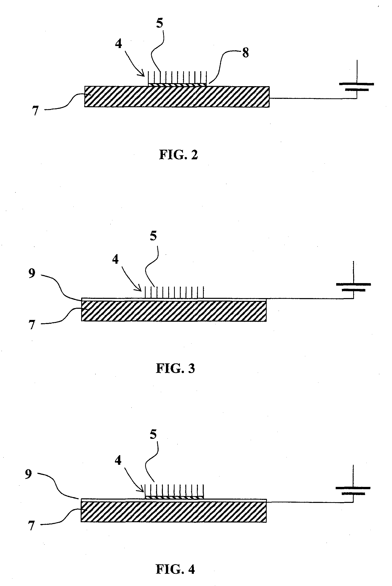
ther alternative embodiment of an electron substrate and an extraction grid of the electron source from FIG. 9;

[0036]FIG. 12 is a schematic view of the electron source from FIG. 1 with a shield;

[0037]FIG. 13 is a synoptic view of the assembly units of a gas detector;

[0038]FIG. 14 is a pulse diagram, which illustrates the time sequence of the electron pulse and of the transfer field pulse during the operation of the sensor from FIG. 13;

[0039]FIG. 15 is a diagram showing the time course of the recombination of reactant ions and analyte ions in the reaction chamber of the gas sensor from FIG. 13;

[0040]FIG. 16 is a view of an application of the gas sensor from FIG. 13;

[0041]FIG. 17 is another possible pulse diagram during the operation of the gas sensor from FIG. 13; and

[0042]FIG. 18 is an exemplary embodiment of the construction of the gas sensor from FIG. 13.

DESCRIPTION OF THE PREFERRED EMBODIMENTS

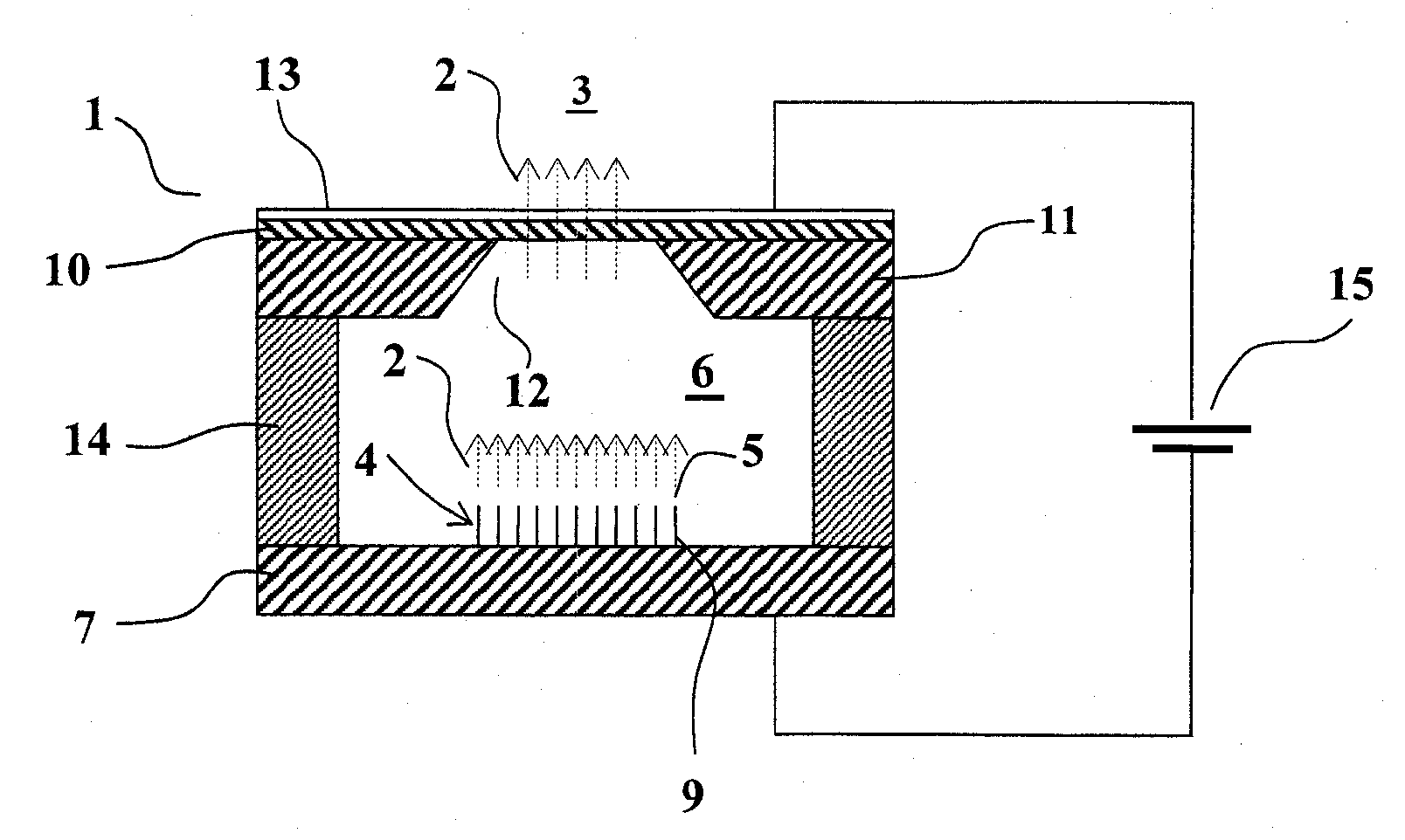
[0043]Referring to the drawings in particular, FIG. 1 schematically shows the constructi...


PUM

PropertyMeasurementUnit
time offsetaaaaaaaaaa
lengthsaaaaaaaaaa

Abstract

A gas detector (25) has an electron source (1), which emits electron pulses into a reaction chamber (26) through a membrane (10). The ions formed in the reaction chamber (26) by the electron beam can be detected by means of a current detector (30) by a transfer field pulse being generated in the reaction chamber. The gas sensor (25) may have especially a miniaturized design.

Description

CROSS REFERENCE TO RELATED APPLICATIONS[0001]This application claims the benefit of priority under 35 U.S.C. §119 of German Patent Application DE 10 2009 051 069.9 filed Oct. 28, 2009, the entire contents of which are incorporated herein by reference.FIELD OF THE INVENTION[0002]The present invention pertains to a gas detector for monitoring the concentration of a gas with a reaction chamber, to which the gas to be monitored can be fed, a pulsable electron source, by which electrons can be emitted in electron pulses into the reaction chamber, a field generator, by which a pulsed electric transfer field can be generated in the reaction chamber, a current detector, by which an ionic current caused by the electrons in the reaction chamber and the transfer field in the reaction chamber can be detected, and with a measuring device, which is arranged downstream of the current detector and by which the ionic current can be quantitatively determined.BACKGROUND OF THE INVENTION[0003]Such a ga...

Claims


Application Information

Patent Timeline
Patent Type & Authority Applications(United States)
IPC IPC(8): G01N27/62G01N27/00B82Y30/00
CPCG01N27/66G01N30/72H01J49/0013H01J49/022
Inventor BATHER, WOLFGANGZIMMERMANN, STEFAN
Owner DRAGERWERK AG
Why Eureka
Try Eureka