Eureka AIR delivers breakthrough ideas for toughest innovation challenges, trusted by R&D personnel around the world.

Control circuits and methods for switching mode power supplies

a control circuit and power supply technology, applied in the direction of power conversion systems, dc-dc conversion, instruments, etc., can solve the problems of many limitations and reduce the switching frequency, and achieve the effect of reducing the output voltage undershoo

Active Publication Date: 2011-04-28
BCD SHANGHAI MICRO ELECTRONICS CO LTD
View PDF25 Cites 95 Cited by
  • Summary
  • Abstract
  • Description
  • Claims
  • Application Information

AI Technical Summary

Benefits of technology

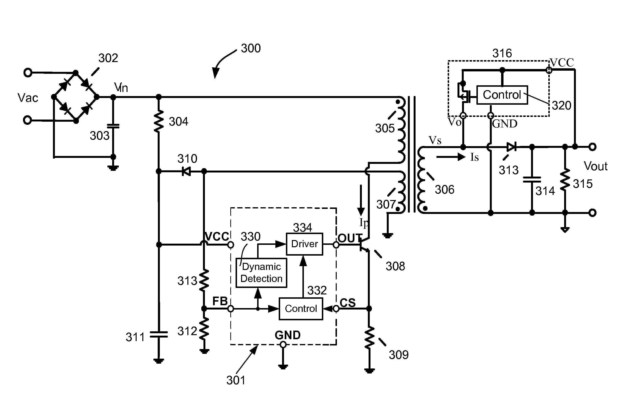
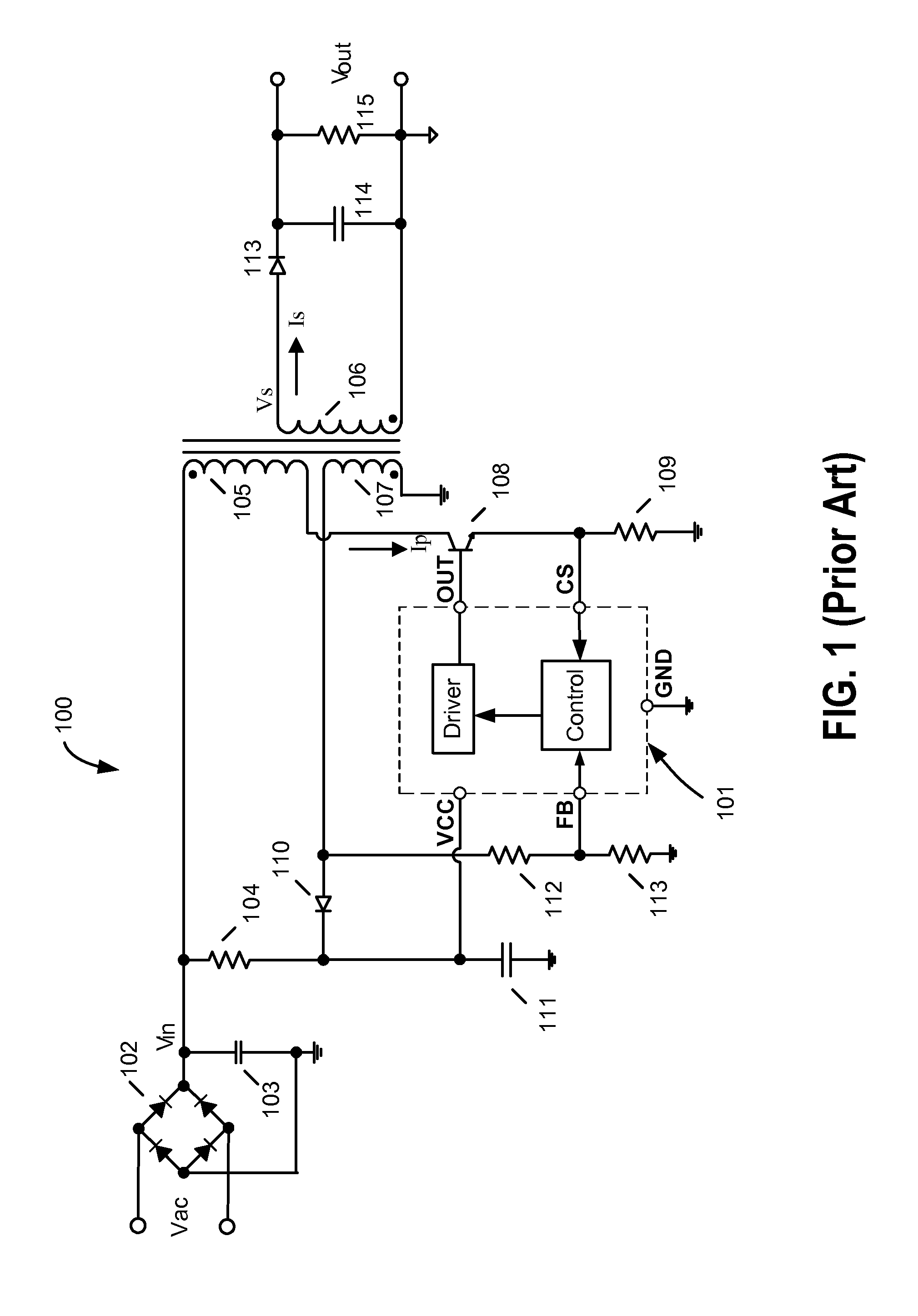
[0006]In accordance with embodiments of the present invention, a variety of techniques are described for transferring system output status through a transformer when the transformer is in a discontinuous conduction mode (DCM) and for reducing the output voltage undershoot during load transient or dynamic load change of switching mode power supplies.
[0015]In still another embodiment of the present invention, the secondary side IC includes a second comparator for controlling the switch. The second comparator compares the anode voltage and cathode voltage of an integrated diode and turn on the switch if the anode voltage is greater than the cathode voltage for the drain to substrate diode. In one embodiment, the integrated diode is a part of the PMOS or NMOS transistor having the drain being the anode and the source and the bulk substrate being the cathode. The transistor's on-resistance can be made small, whereby the voltage drop across the switch can be lower than 0.5V during the on time of the secondary winding. Then the external rectifying diode can be eliminated, and the power supply conversion efficiency is increased because the switch will dissipate less power than the external rectifying diode, whose forward conduction voltage is about 0.5V. In yet another embodiment, the second comparator is an offset comparator.

Problems solved by technology

However, reducing switching frequency in an SMPS can also lead to many limitations.

Method used


Image

  • Control circuits and methods for switching mode power supplies
  • Control circuits and methods for switching mode power supplies
  • Control circuits and methods for switching mode power supplies

Examples


Embodiment Construction

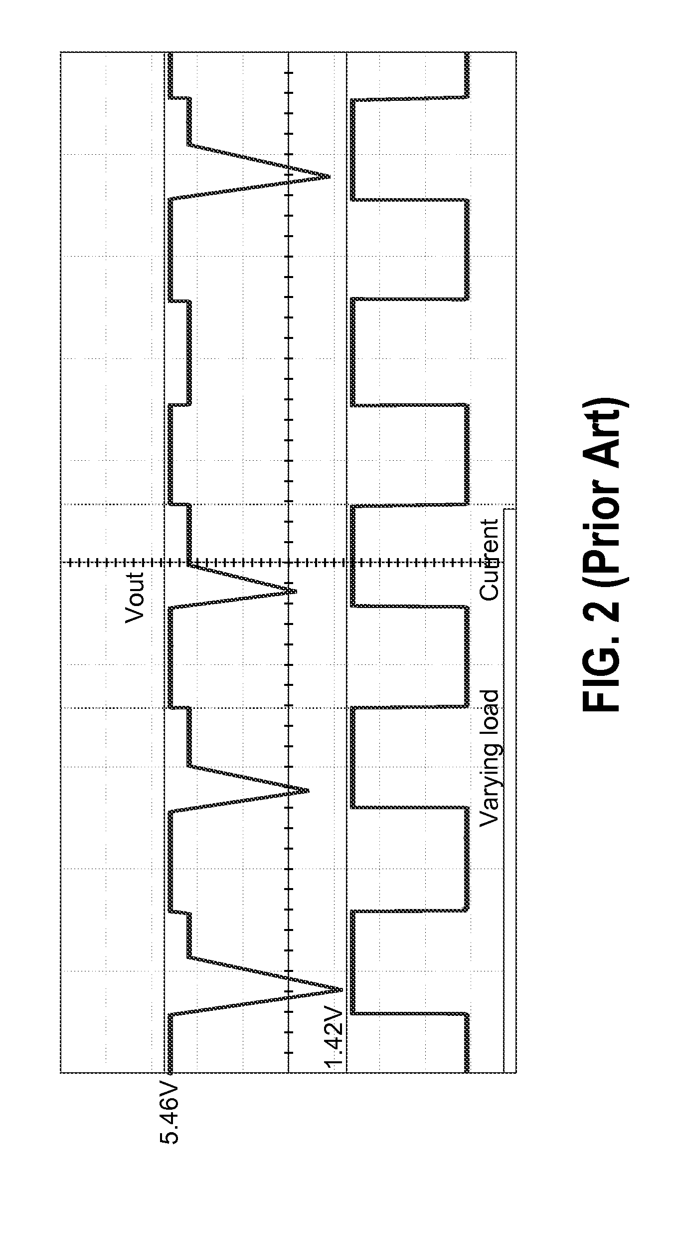
[0032]As described above, new energy efficiency requirements have led to continued reduction of switching frequency in SMPS. But slower switching frequency in light load or no load conditions results in a slower response to system output load transients from light loads to heavy loads, which can lead to a large system output voltage undershoot during a single load transient, or periodic load transients between no load to full load. As used herein, the term “dynamic load changes” refers to rapidly changes in output voltage and / or current at the system output.

[0033]Restrain output voltage spike during load transient or dynamic load change within a specific range is often desired in an SMPS. For example, some specifications of mobile phones require that the charger output voltage must be higher than 4.2V when the output current varies within a range from 0 mA to 700 mA. Some notebook computers or LCD TVs may also require that adapters have output voltages that vary less than + / −10 perc...


PUM


Abstract

Circuits and method for sensing a system output voltage change and transmitting an electrical signal to an auxiliary winding on the primary side. In an embodiment, a primary side controller detects the electrical signal and turns a power switch on and off to transfer energy from a primary winding to a secondary winding. A secondary side controller generates a voltage pulse at a terminal of the secondary winding when the system output voltage is below a reference voltage. The secondary side controller includes an input terminal connected to a system output, an output terminal connected to a terminal of the secondary winding, and a ground terminal connected to a ground potential of the system output.

Description

CROSS-REFERENCES TO RELATED APPLICATIONS[0001]This application is related to U.S. patent application Ser. No. 12 / 248,665, filed Oct. 9, 2008, entitled “METHOD AND APPARATUS FOR REDUCING STANDBY POWER OF WITCHING MODE POWER SUPPLIES” by inventors Yajiang Zhu et al., commonly assigned and incorporated by reference herein for all purposes.[0002]This application is also related to U.S. patent application Ser. No. 12 / 136,760, filed Jun. 11, 2008, entitled “METHOD AND SYSTEM FOR PULSE FREQUENCY MODULATED SWITCHING MODE POWER SUPPLIES” by inventors Yajiang Zhu et al., commonly assigned and incorporated by reference herein for all purposes.BACKGROUND OF THE INVENTION[0003]The present invention is directed to switching mode power supplies (SMPS). More particularly, embodiments of the invention provide circuits and methods of transferring system output status through the transformer. Merely by way of example, the invention has been applied to control the output voltage undershoot of a pulse w...

Claims


Application Information

Patent Timeline
Patent Type & Authority Applications(United States)
IPC IPC(8): H02M3/335
CPCH02M3/33523H02M3/33507
Inventor ZHU, YAJIANGXIE, JIAZHANG, YONGBOCHEN, CHAOLV, SHUZHUANG
Owner BCD SHANGHAI MICRO ELECTRONICS CO LTD
Why Eureka
Eureka Blog
Learn More