
Liquid Crystal Device

a liquid crystal device and liquid crystal technology, applied in static indicating devices, instruments, non-linear optics, etc., can solve the problems of inevitably reducing the reliability of mechanical devices, accelerating the speed of three-, selective invisibility and light control, and becoming speedy and complicated

Inactive Publication Date: 2011-04-28
NANO LOA
View PDF5 Cites 8 Cited by
  • Summary
  • Abstract
  • Description
  • Claims
  • Application Information

AI Technical Summary

Benefits of technology

[0013]Another object of the present invention is to provide a liquid crystal device having a temperature compensation function capable of achieving a good light / dark ratio condition.
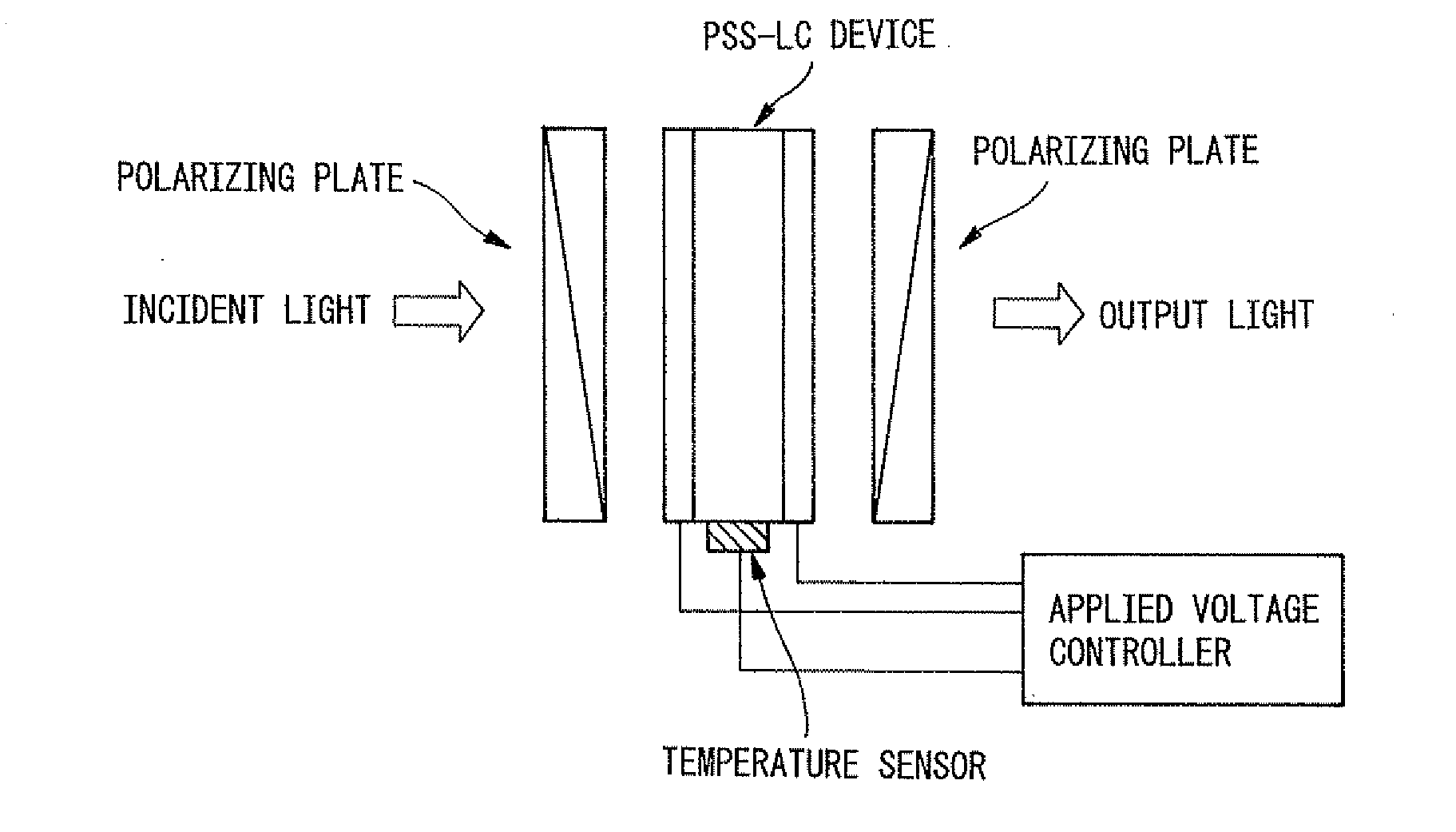
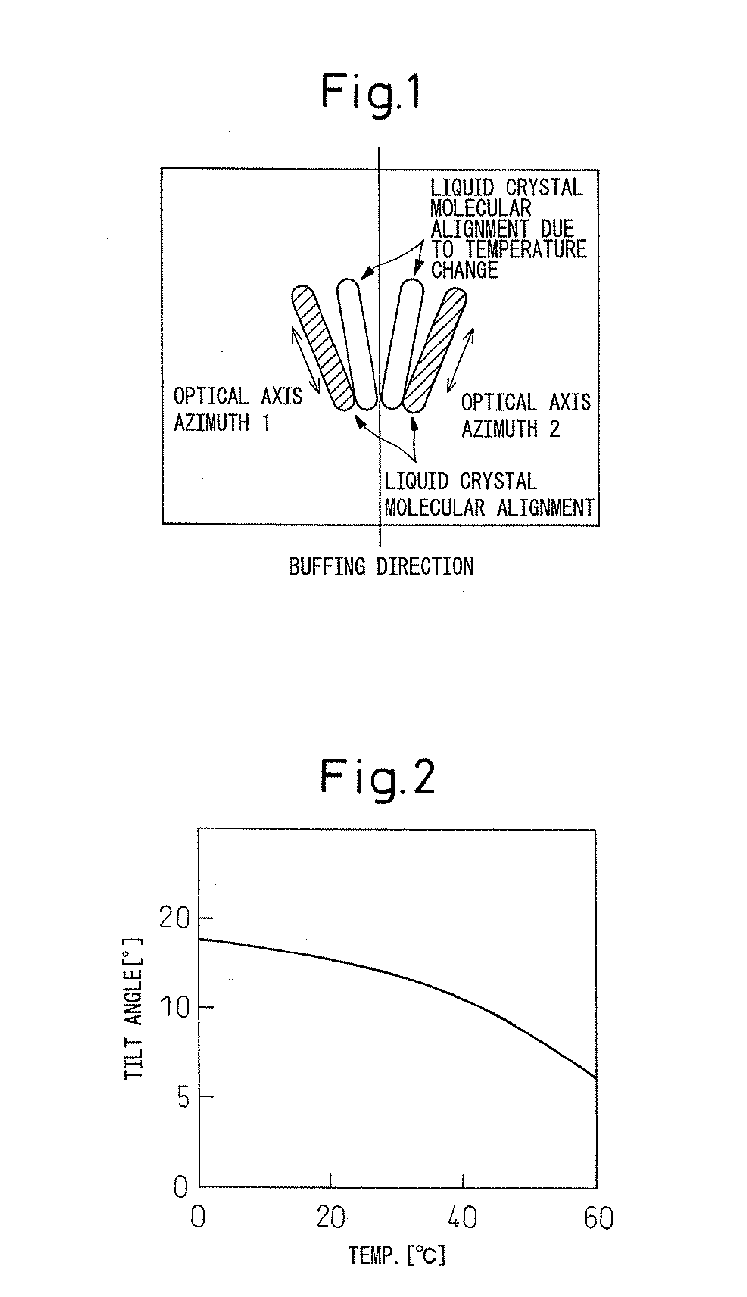
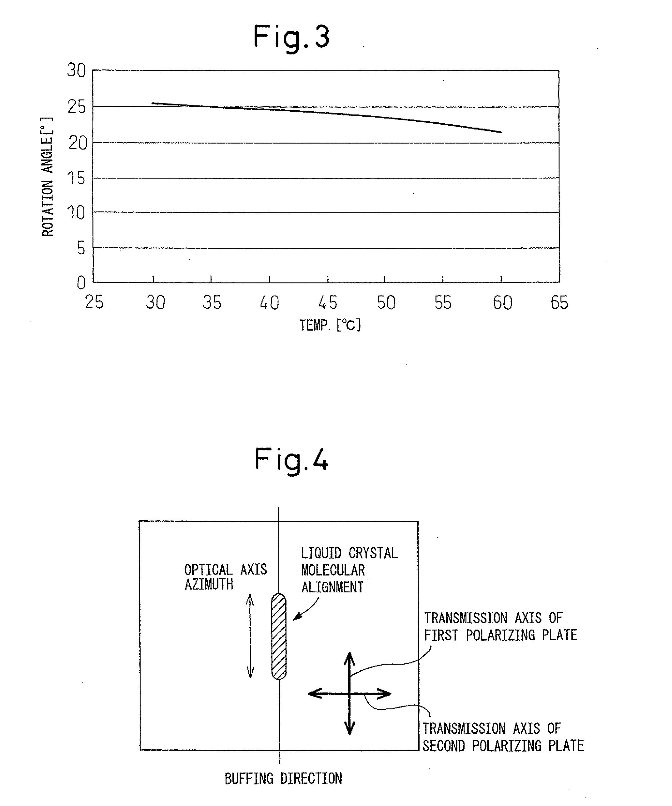
[0041]Generally, in the case of an analog gradation LCD where liquid crystal molecules switch their direction in the same plane parallel to the buffing direction, the transmitted light quantity has temperature dependency. In the present invention, such temperature dependency can be reduced. In the above-described PSS-LCD device (PSS-LCD), liquid crystal molecules move quickly and therefore, such temperature dependency tends to be relatively strong.

Problems solved by technology

In order to meet these needs, also in the field of visual display and depiction, the display image processing technique such as three-dimensional display, selective invisibility and light control is rapidly advancing and becoming speeded-up and complicated.
Furthermore, the above-described device having a conventional mechanical mechanism is subject to wear in its rocking portion to some degree or another, and the reliability of the mechanical device inevitably tends to decrease.
Above all, in an application where the device is used at such a high speed level as clicking the shutter several tens of times or more for 1 second, the rocking portion is worn to a significant extent.
Of course, fairly severe vibration or noise is generated from the worn portion or the actuator portion such as motor or piezoelectric / electrostrictive element.
However, these electro-optical devices are not free of a problem.
For example, in the case of a PLZT (lead lanthanum-added zirconate titanate) crystal having an electro-optical effect, a driving voltage of several hundreds of V is necessary for obtaining a sufficiently high transmittance and depending on the electrode structure of the optical shutter, breakdown may occur due to the high voltage.
Also, by the nature as a crystal, this device has a strong tendency that growth in size is difficult, as compared with a liquid crystal enabling production of a large-screen display of even 100 inches.
Also, in the case of a device using a TN liquid crystal, the driving voltage for operation may be a low voltage of several V, but the response speed is as low as approximately several tens of ms and although the “rising up” may be improved by applying a high voltage, the “rising down” is not improved, making the high-speed operation to still remain difficult.
In the light of high-speed response and low voltage, use of a ferroelectric liquid crystal may be considered, but the ferroelectric liquid crystal has spontaneous polarization and its driving disadvantageously requires a large amount of current compared with TN liquid crystal and the like.
As the method for such temperature compensation, various devices in accordance with the stable position “slipped” from the original position due to the ambient temperature are required, and the construction of the liquid crystal device or optical shutter inevitably becomes complicated.

Method used


Image

  • Liquid Crystal Device
  • Liquid Crystal Device
  • Liquid Crystal Device

Examples


embodiment 1

of Liquid Crystal Device

[0108]In one embodiment of the present invention, the liquid crystal device comprises at least a pair of polarizing elements with respective transmission axes being perpendicular to each other, a liquid crystal element disposed between the pair of polarizing elements, and voltage applying means for applying a voltage to the liquid crystal element. The liquid crystal element is a liquid crystal element which comprises at least a pair of substrates and a liquid crystal material disposed between the pair of substrates and at the same time, in which the liquid crystal material can rotate the optical axis azimuth in response to the strength and / or direction of an electric field to be applied thereto. Furthermore, the voltage applying means is voltage applying means capable of controlling a voltage to be applied from the voltage applying means to the liquid crystal element in accordance with the liquid crystal molecular alignment in the liquid crystal material.

embodiment 2

of Liquid Crystal Device

[0109]In another embodiment of the present invention, the liquid crystal device is a liquid crystal device comprising at least a pair of polarizing elements being disposed so that the transmission axes thereof are perpendicular to each other, a liquid crystal element disposed between the pair of polarizing elements, and angle adjusting means for adjusting the angle between the liquid crystal element and the polarizing element. The liquid crystal element is a liquid crystal element which comprises at least a pair of substrates and a liquid crystal material disposed between the pair of substrates and at the same time, in which the liquid crystal material can rotate the optical axis azimuth in response to the strength and / or direction of an electric field to be applied thereto. Furthermore, the angle adjusting means is angle adjusting means capable of controlling the angle between the liquid crystal element and the polarizing element in accordance with the liqui...

production example 1

[0221]Using commercially available FLC mixture material (Merck: ZLI-4851-100), photo-curable liquid crystalline material (Dai-Nippon Ink Chemicals: UCL-001), and photo initiator material (Merck: Darocur 1173), based on JP-A H11-21554 (Japanese Paten Appln. H09-174463), PS- V-FLCD panel was fabricated. The mixture had 93 mass % of ZLI-4851-100 FLC mixture, 6 mass % of UCL-001, and 1 mass % Darocur 1173.

[0222]The substrate used herein was a glass substrate (borosilicate glass, thickness 0.7 mm, size: 50 mm×50 mm; available from Nano Loa Inc.) having thereon an ITO film.

[0223]The polyimide alignment film was formed by applying a polyimide alignment material by use of a spin coater, then preliminarily baking the resultant film, and finally baking the resultant product in a clean oven. With respect to the details of the general industrial procedure to be used herein, as desired, a publication “Liquid Crystal Display Techniques”, Sangyo Tosho (1996, Tokyo), Chapter 6 may be referred to.

[0...


PUM


Abstract

A liquid crystal device, comprising, at least, a pair of polarizing elements being disposed so that the transmission axes thereof are perpendicular to each other; a liquid crystal element disposed between the pair of polarizing elements; and voltage applying means for applying a voltage to the liquid crystal element. The liquid crystal element is such that it enables high-speed optical response, and the optical axis azimuth thereof is rotatable in response to the strength and / or direction of an electric field to be applied thereto. The voltage applying means is capable of controlling a voltage to be applied from the voltage applying means to the liquid crystal element, in response to the liquid crystal molecular alignment in the liquid crystal material. There is provided a liquid crystal device having a temperature-compensating function so as to achieve a good light-dark ratio.

Description

TECHNICAL FIELD[0001]The present invention relates to a liquid crystal device having a reduced temperature dependency, which is suitably usable for various display devices and the like including an optical shutter device and a display.BACKGROUND ART[0002]In recent years, combined with the progress in technology aiming at a so-called “ubiquitous society”, various needs for the display technique in general, such as high-speed response, downsizing and high display quality, are sophisticated. In order to meet these needs, also in the field of visual display and depiction, the display image processing technique such as three-dimensional display, selective invisibility and light control is rapidly advancing and becoming speeded-up and complicated. On the other hand, improvement of the environment related to information transfer including optical communication using an optical fiber cable or the like is promoted, and attempts are being made to realize large-volume high-speed data or inform...

Claims


Application Information

Patent Timeline
IPC IPC(8): G02F1/133
CPCG02F1/13306G02F2203/21G02F1/141G02F1/133G02F1/1337
Inventor IKEDA, HAJIME
Owner NANO LOA
Learn More