
Device for testing an electrical component

a technology for electrical components and devices, applied in the direction of testing circuits, instruments, program control, etc., can solve the problems of insufficient dielectric strength and insufficient proof voltage, and achieve the effect of improving test results

Active Publication Date: 2011-04-14
DSPACE DIGITAL SIGNAL PROCESSING & CONTROL ENG
View PDF4 Cites 2 Cited by
  • Summary
  • Abstract
  • Description
  • Claims
  • Application Information

AI Technical Summary

Benefits of technology

[0008]It is therefore an object of the present invention to provide a device for testing an electrical component, which provides improved test results.
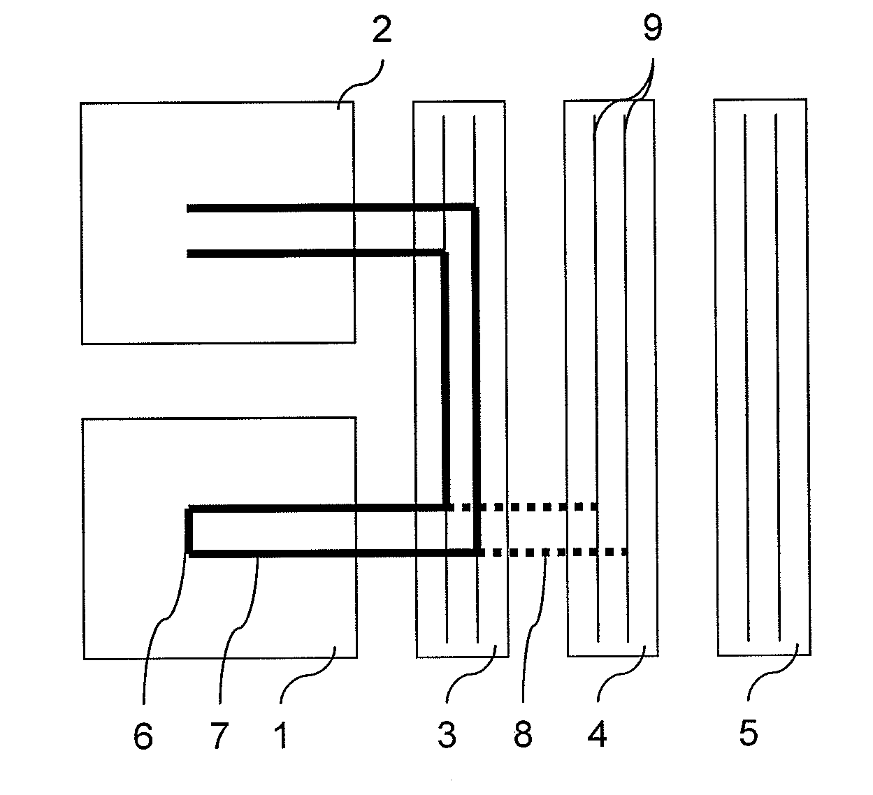
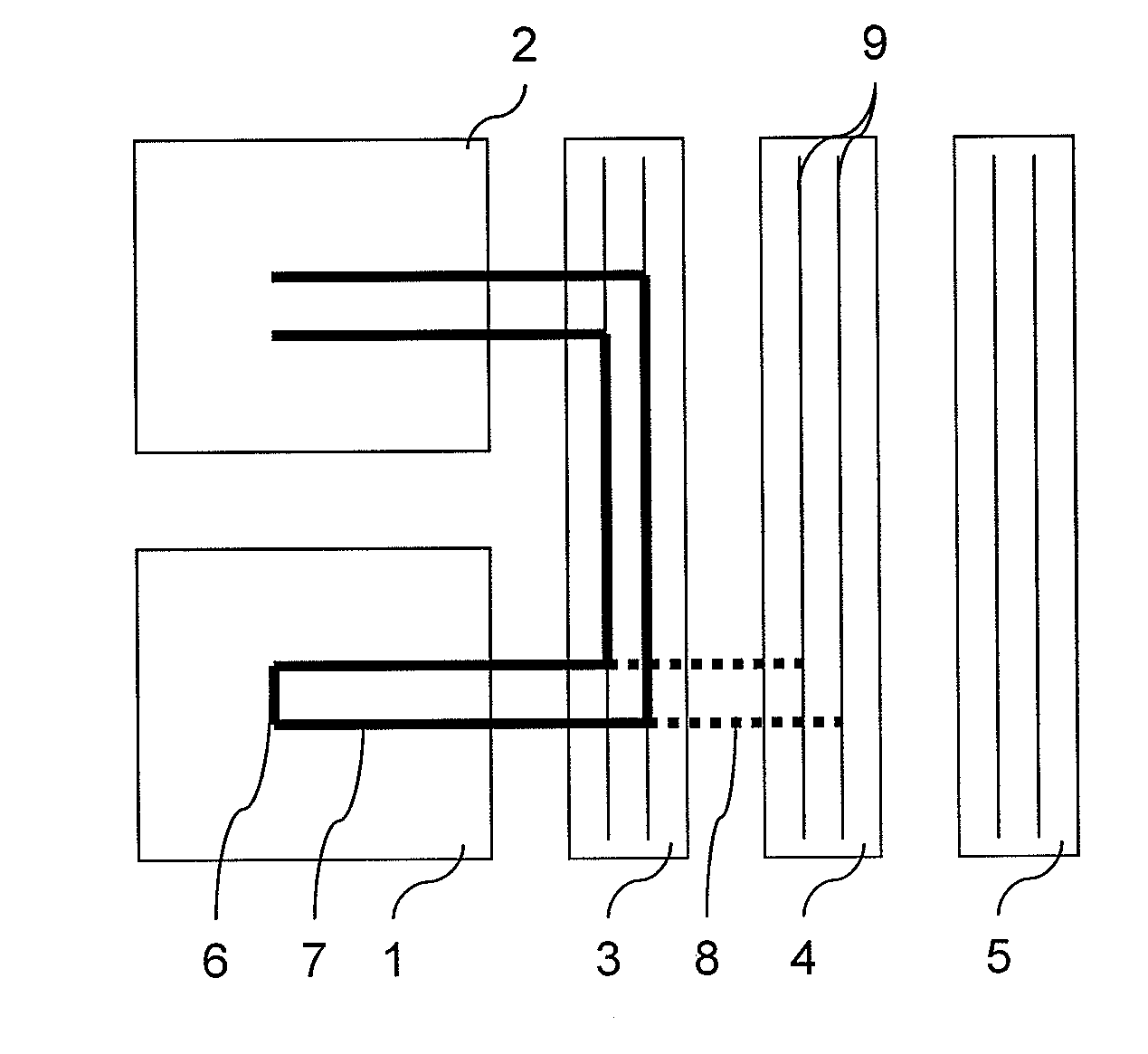
[0011]The invention therefore enables connecting the simulation device and the testing device to a “simulation signal-specific” connecting device by means of the selection device, which can be made, for example, as a switch, in such a way that the signal corruption due to the parasitic property of the connecting device for the simulation signal generated by the simulation device is especially low. In this respect, different types of simulation signals can be assigned to different connecting devices, whereby the particular connecting device during supplying with the particular simulation signal causes only minor or no changes or disruptions in the simulation signal. It is achieved thereby, that the test results become more accurate, because unwanted effects due to the parasitic property of the connecting devices are reduced. Preferably, the selection of the connecting device occurs by means of the selection device based on at least one predefinable parameter, such as, for example, based on a table, based on a measurement, and / or based on a computer program.
[0012]In this connection, an embodiment of the invention provides that the electrical property of at least one of the connecting devices is selected in such a way that the signal corruption due to a parasitic property of the connecting device is minimized for a particular simulation signal. The electrical properties of all connecting devices can be selected in such a way that the signal corruption due to the parasitic property of a particular connecting device is minimized for a particular simulation signal. In other words, therefore, different “signal classes” of simulation signals can be assigned to different connecting devices, so that the noise components arising due to the parasitic properties of the connecting devices are reduced, preferably minimized, for the particular simulation signal.
[0016]Basically, any number of connecting devices can be provided. According to an embodiment of the invention, at least two connecting devices are provided and the electrical property of the first connecting device and the second connecting device is selected in such a way that at a high current the signal corruption due to the parasitic property of the first connecting device is smaller than the signal corruption due to the parasitic property of the second connecting device or at a low current the signal corruption due to the parasitic property of the first connecting device is greater than the signal corruption due to the parasitic property of the second connecting device and / or at a high voltage the signal corruption due to the parasitic property of the first connecting device is smaller than the signal corruption due to the parasitic property of the second connecting device or at a low voltage the signal corruption due to the parasitic property of the first connecting device is greater than the signal corruption due to the parasitic property of the second connecting device. In other words, for example, the electrical properties of the first connecting device and the second connecting device are selected in such a way that at a high current the signal corruption due to the parasitic property of the first connecting device is smaller than the signal corruption due to the parasitic property of the second connecting device. According to this example, therefore, more accurate test results can be achieved with the use of the first connecting device, because the signal corruption due to the parasitic property, which has an interfering or modifying effect on the simulation signal, at a high current is smaller for the first connecting device than for the second connecting device. Accordingly, the accuracy in tests of electrical components can be increased by the invention in a simple way by the use of a plurality of connecting devices each with electrical properties different from one another.
[0029]The accuracy of an HIL simulation can be improved by the device of the invention, because the parasitic properties of the connecting devices can be minimized.

Problems solved by technology

The parasitic property of a connecting device include in particular also an insufficient dielectric strength or an insufficient proof voltage of the connecting device, whereby the dielectric strength or proof voltage of the connecting device depends substantially on the insulation material and substance, and / or the insulator geometry, therefore, for example, the thickness of an insulator surrounding the electrical conductor.

Method used


Image

  • Device for testing an electrical component
  • Device for testing an electrical component

Examples


Embodiment Construction

[0032]A device for testing an electrical component, such as, for example, a control system for a motor vehicle or an automation device, according to a preferred exemplary embodiment of the invention, can be seen in a schematic illustration in the FIGURE. The device has a simulation device 1, a testing device 2, and three connecting devices 3, 4, 5.

[0033]A simulation signal, with which an error-free and / or a faulty operating state of the electrical component can be simulated, can be generated by simulation device 1. The simulation signal can have a current and / or a voltage, whereby in addition a resistive component, a capacitive component, an inductive component, and / or a frequency component can be present in the current and / or in the voltage. In the present case, simulation device 1 comprises a failure insertion unit, abbreviated as FIU. Further, the simulation signal can be a short circuit, as is indicated by line 6.

[0034]Testing device 2 is used to connect the electrical component...


PUM


Abstract

A device for testing an electrical component is provided, having a simulation device for generating a simulation signal, a testing device for connecting the electrical component, at least two connecting devices, and a selection device for selecting the connecting device, wherein the simulation device and the testing device can be connected in an electrically conducting manner to at least one of the connecting devices by the selection device and the individual connecting devices differ from one another in at least one electrical property. Thus, a device for testing an electrical component is provided with which in a simple manner the testing accuracy can be increased by minimizing the signal corruption due to a parasitic property of the connecting device.

Description

[0001]This nonprovisional application claims priority under 35 U.S.C. §119(a) to German Patent Application No. DE 10 2009 048 981.9, which was filed in Germany on Oct. 9, 2009, and which is herein incorporated by reference.BACKGROUND OF THE INVENTION[0002]1. Field of the Invention[0003]The invention relates to a device for testing an electrical component.[0004]2. Description of the Background Art[0005]Devices for testing electrical components, such as, for example, of a control system for a motor vehicle or an automation device, are known from the conventional art and have highly different designs and are used primarily in applied research, industrial development, and in other areas of application, particularly in the fields of mechatronics, automotive applications, in air and space technology, in systems and process engineering, and other technical fields in which process control tasks must be solved in the broadest sense. In this respect, a control system in this context is unders...

Claims


Application Information

Patent Timeline
IPC IPC(8): G06F17/50
CPCG05B2219/23446G05B19/0426
Inventor HASSE, DIRKSCHEIBELHUT, PETERBITTNER, DIRKPOLNAU, ROBERT
Owner DSPACE DIGITAL SIGNAL PROCESSING & CONTROL ENG
Learn More