Differential signaling cable, transmission cable assembly using same, and production method for differential signaling cable
- Summary
- Abstract
- Description
- Claims
- Application Information
AI Technical Summary
Benefits of technology
Problems solved by technology
Method used
Image
Examples
first embodiment
of Present Invention
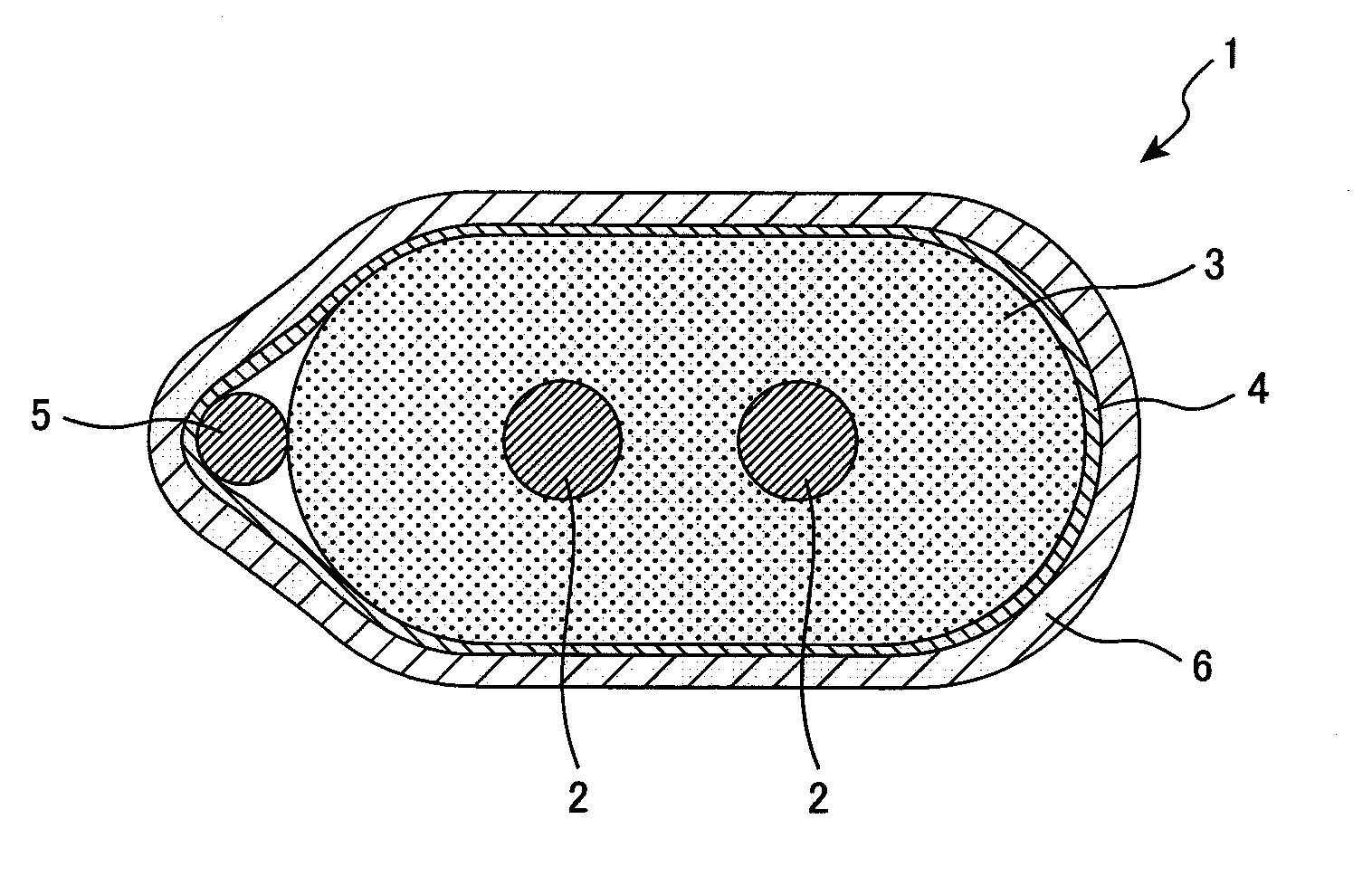
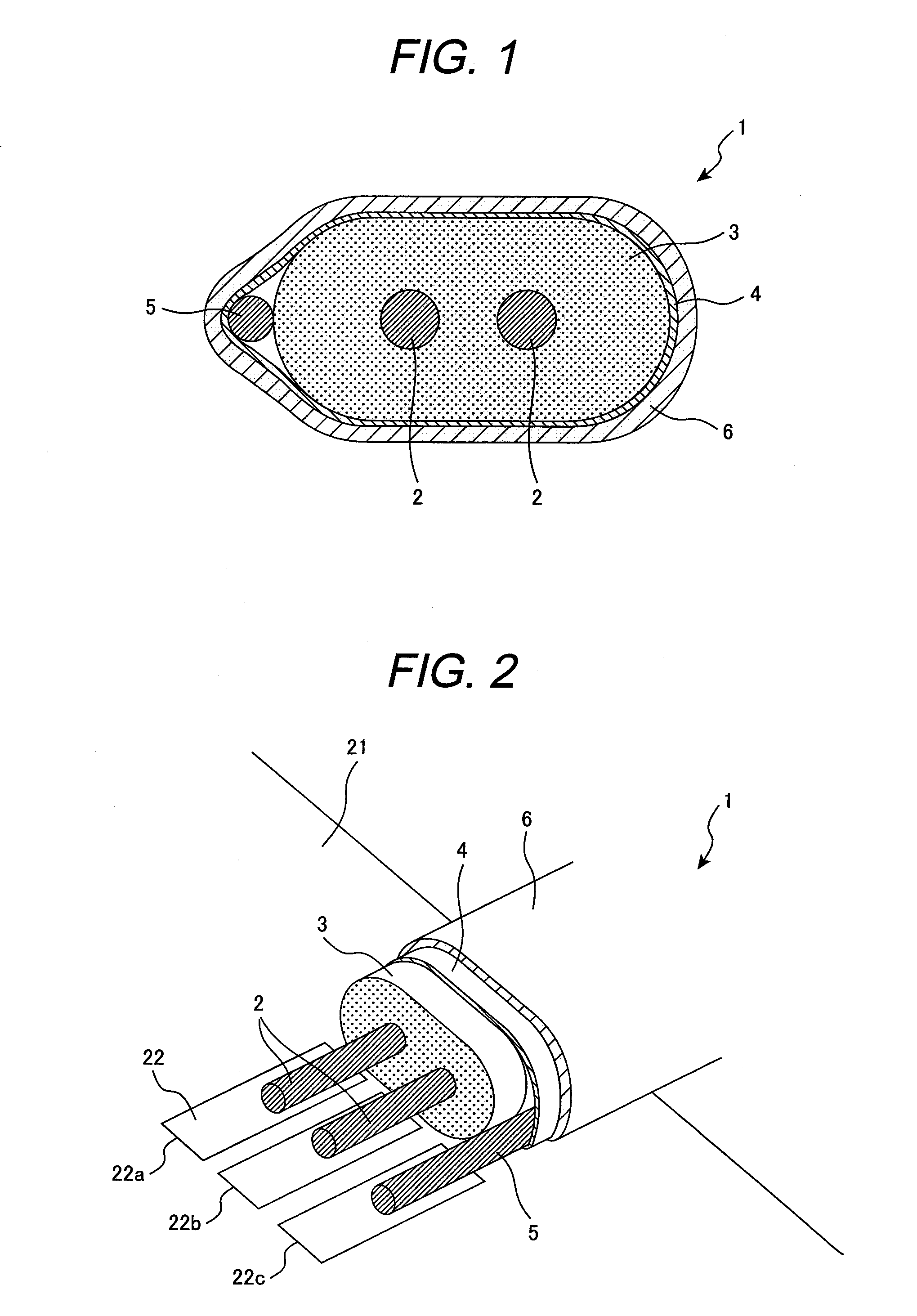
[0047]FIG. 1 is a schematic illustration showing a cross-sectional view of an exemplary differential signaling cable according to a first embodiment of the present invention. As shown in FIG. 1, a differential signaling cable 1 comprises: a pair of signal conductors 2 provided in parallel; an insulator 3 having a predetermined permittivity which covers in a batch the periphery of both signal conductors 2; a shield conductor 4 provided on the outer periphery of the insulator 3; a drain wire 5 for grounding longitudinally disposed between the insulator 3 and the shield conductor 4; and a jacket 6 for cable protection provided on the outer periphery of the shield conductor 4.
[0048]The signal conductor 2 is a good electrical conductor made of copper or the like. Furthermore, the signal conductor 2 is a single wire or a twisted wire made by plating a metal on the good electrical conductor. In a differential signaling cable 1 according to this embodiment, an interval b...
second embodiment
of Present Invention
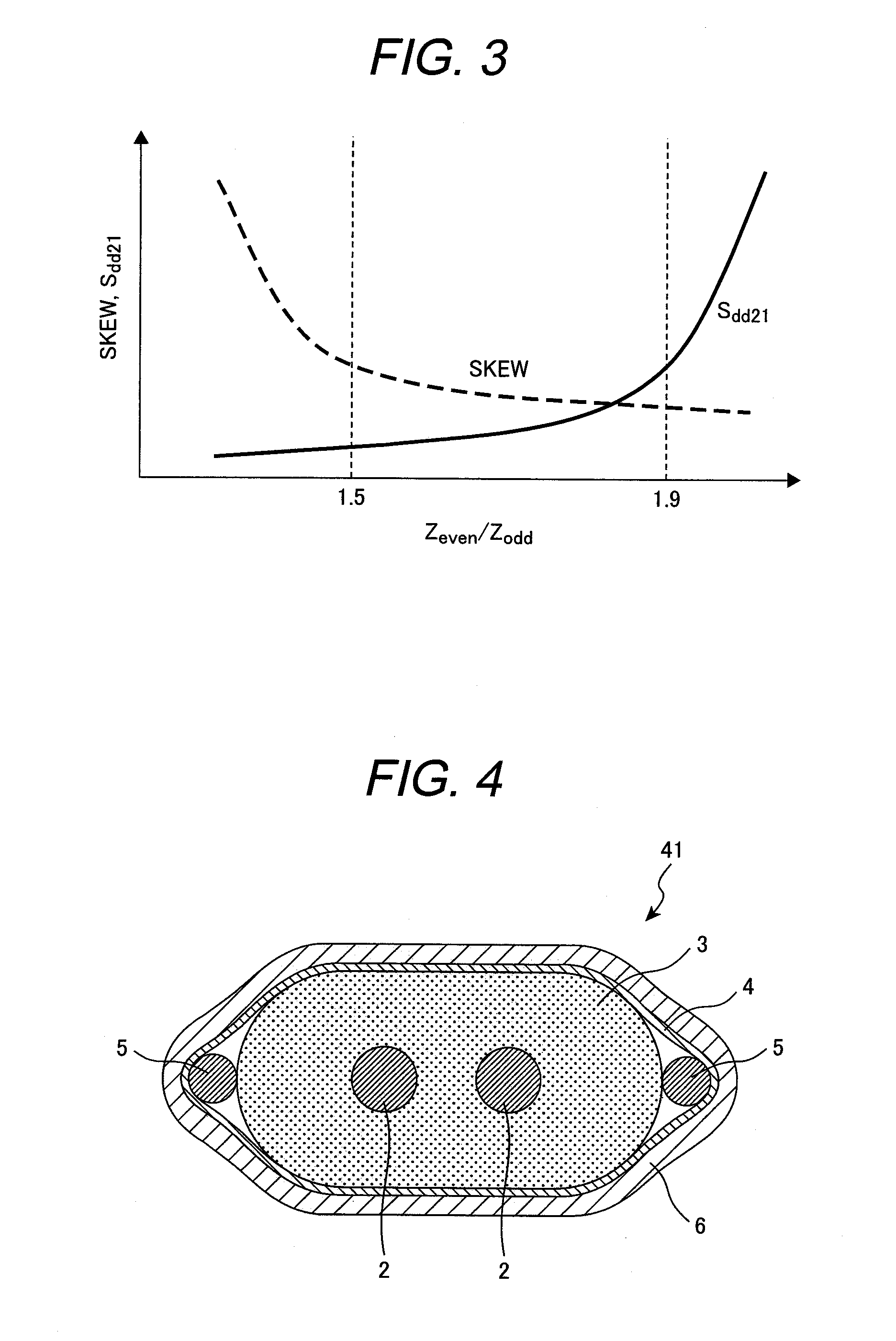
[0071]FIG. 4 is a schematic illustration showing a cross-sectional view of an exemplary differential signaling cable according to a second embodiment of the present invention. A differential signaling cable 41 shown in FIG. 4 has the same structure as that of the differential signaling cable shown in FIG. 1, and the difference is that a drain wire 5 is disposed on both the right and left side of the insulator 3 in the differential signaling cable 41. Both drain wires 5 and both signal conductors 2 are linearly disposed along the width direction of the insulator 3.
[0072]Because drain wires 5 are located bilaterally symmetrically in the differential signaling cable 41, the bilaterally symmetric property of electromagnetic waves propagating through the signal conductors 2 becomes good, and the skew and the differential-to-common-mode conversion quantity can be further reduced.
third embodiment
of Present Invention
[0073]FIG. 5 is a schematic illustration showing a cross-sectional view of an exemplary differential signaling cable according to a third embodiment of the present invention. A differential signaling cable 51 shown in FIG. 5 is structured such that in a differential signaling cable 41 in FIG. 4, an engagement groove 3a with which a drain wire 5 is engaged is formed on the ends on both sides of the insulator 3 in its width direction along the longitudinal direction to securely engage the drain wires 5 with the engagement grooves 3a.
[0074]For example, the engagement groove 3a can be easily formed by providing a protrusion at the ejecting portion of an extruding machine (where an engagement groove 3a is formed) when extrusion molding the insulator 3. The depth of the engagement groove 3a should not be too deep so that the drain wires 5 can be pressed by the shield conductor 4 and the conductive surface (metal foil) of the shield conductor 4 can come in sufficient c...
PUM
 Abstract
Description
Claims
Application Information
 - R&D
- Intellectual Property
- Life Sciences
- Materials
- Tech Scout
- Unparalleled Data Quality
- Higher Quality Content
- 60% Fewer Hallucinations
Browse by: Latest US Patents, China's latest patents, Technical Efficacy Thesaurus, Application Domain, Technology Topic, Popular Technical Reports.
© 2025 PatSnap. All rights reserved.Legal|Privacy policy|Modern Slavery Act Transparency Statement|Sitemap|About US| Contact US: help@patsnap.com


