
Electrowetting Microarray Printing System and Methods for Bioactive Tissue Construct Manufacturing

a printing system and microarray technology, applied in the direction of specific use bioreactors/fermenters, biomass after-treatment, enzymology, etc., can solve the problems of limited control of seeding, limited control of microarchitecture, and inability to achieve heterogeneous cell patterning

Inactive Publication Date: 2011-03-31
DUKE UNIV +1
View PDF3 Cites 51 Cited by
  • Summary
  • Abstract
  • Description
  • Claims
  • Application Information

AI Technical Summary

Benefits of technology

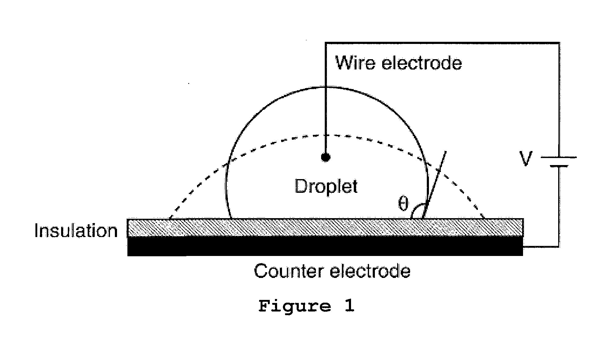
[0020]FIG. 1 depicts the principle of EWOD. In EWOD, a droplet of liquid rests on a surface or in a channel coated with a hydrophobic, dielectric material. Charge accumulates at the solid-liquid interface, and the surface wettability is modified from hydrophobic to hydrophilic by applying a voltage between the liquid and an electrode under the dielectric layer. EWOD uses the change in contact angle direction to induce liquid motions.
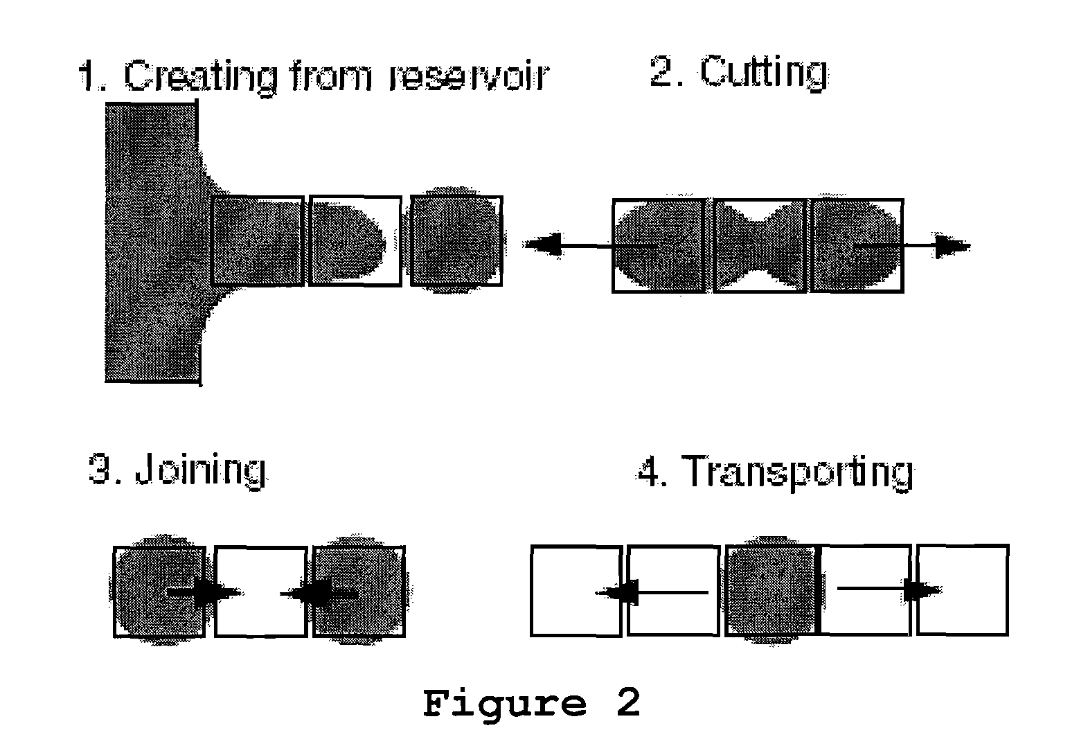
[0021]FIG. 2 depicts fundamental droplet operations. Droplets are ejected from reservoirs and programmed to move to specific, discrete target locations where they can be positioned, or merged, or cut. By applying a sequence of voltage to electrodes patterned under the dielectric layer, four fundamental droplet manipulation mechanisms can be established (FIG. 2): (1) creating, (2) cutting, (3) joining, and (4) transporting of droplets from a reservoir and in the fluid path.

Problems solved by technology

Non-automation methods have the advantages of simplicity and low cost, but the control over the microarchitecture is limited to approximate control of pore size for cast hydrogels, and fiber size and planar orientation (linear or random mats) for fibrous networks.
Further, control of seeding is limited to cell density control and heterogeneous cell patterning cannot be achieved.
In most non-automation methods, an internal porous structure is generated by randomly packed porogen and cannot be controlled precisely or flexibly.
For example, the pore size and porosity at different sections of the scaffold should be different in many cases, and all the pores should be interconnected; however, these requirements cannot be obtained or guaranteed.
The biggest limitation with these methods is their incapability for making complex 3D multicellular constructs, as well as their incapability for incorporating a vascular network.
Second, SFF technology makes parts in an additive fashion through a layer-by-layer process.
2004, Trends in Biotechnology, 22), but the potential of SFF has not yet been fully exploited for soft tissue engineering yet.
These systems can function only in a narrow, low viscosity range, which limits the type and strength of solutions that can be printed.
In addition, inkjet printers have problems with cells clogging the jets, have a resolution limited to about 200 μm and are not well-suited for dispensing living cells, based on the 25% cell death that has been reported (Wilson & Boland, 2003, Anat Rec A Discov Mol Cell Evol Biol 272:491-496).
This process also includes an extra step of using an intermediate substrate “bio paper” to support cells, because the process cannot jet out hydrogel along with cells, which limits the prospects of this method for 3D printing.
Extrusion-based SFF methods produce a limited range of scaffold architectures, with parallel linear elements stacked in layers, at a resolution of around 100 μm, and do not enable heterogeneous cell patterning (precise arrangement of multiple cell types).
SFF methods also may not scale up easily to 3D manufacturing because cells are usually delivered from 2D arrays.

Method used


Image

  • Electrowetting Microarray Printing System and Methods for Bioactive Tissue Construct Manufacturing
  • Electrowetting Microarray Printing System and Methods for Bioactive Tissue Construct Manufacturing
  • Electrowetting Microarray Printing System and Methods for Bioactive Tissue Construct Manufacturing

Examples


experimental examples

[0142]The invention is further described in detail by reference to the following experimental examples. These examples are provided for purposes of illustration only, and are not intended to be limiting unless otherwise specified. Thus, the invention should in no way be construed as being limited to the following examples, but rather, should be construed to encompass any and all variations which become evident as a result of the teaching provided herein.

[0143]The materials and methods employed in the experiments disclosed herein are now described.

example 1

Hydrogel Dispensing

[0144]The capability of EWOD to dispense hydrogels has been assessed as follows. Several solutions were mixed, filtered, and then used as described below: a 1% w / v sodium alginate, a 2% w / v sodium alginate with a viscosity of 250 cP at 25° C., and a 1% w / v calcium chloride solution. The experiments described herein were performed on a glass chip with patterned chrome electrodes, having a pitch of 0.75 mm and a gasket to maintain top-plate height above the electrodes. The chip was first coated with Parylene C, which functions as a dielectric and chemical insulator, and then was coated with a thin layer of Teflon AF for hydrophobicity. The top plate consisted of a sputtered indium-tin oxide (ITO)-coated film, which was later coated with Teflon AF for hydrophobicity. ITO is a transparent conductor, allowing the top plate to remain grounded during operation. All of the experiments were performed at room temperature.

[0145]First, experiments were conducted to determine ...

example 2

Cell Manipulation on EWOD Chip

[0147]The capability of the EWOD process for handling, dispensing and actuating cell suspensions was examined. Further, the voltage that can be applied to cells without damaging them was examined.

[0148]Tests were conducted on the EWOD chip using the human fetal osteoblast cell line hFOBs 1.19 (obtained from ATCC between passage 11 and 13). Cells were cultured in Dulbecco's Modified Eagles Medium (DMEM) containing 10% FBS and 1% Penicillin-Streptomycin prior to the experiment. Cultured cells were trypsinised, suspended in PBS and separated by centrifuging. The separated cells were treated with a Live Dead Assay (Molecular Probes) reagent solution (6 μM ethidium homodimer-1 and 2 μM Calcein in PBS) according to the manufacturer's instructions. The cell suspension was loaded on chips, which were actuated with voltages ranging from 40-60 V. After actuation the EWOD chips were observed under fluorescent microscope to quantify live and dead cells. The fractio...


PUM

PropertyMeasurementUnit
actuation voltageaaaaaaaaaa
sizesaaaaaaaaaa
sizeaaaaaaaaaa

Abstract

Apparatuses and methods for manufacturing three-dimensional, bioactive, tissue scaffold fabrications with embedded cells and bioactive materials, such as growth factors, using biomimetic structure modeling, solid freeform fabrication, biocompatible hydrogel material, and electrowetting on dielectric-based multi-microarray printing.

Description

STATEMENT REGARDING FEDERALLY SPONSORED RESEARCH OR DEVELOPMENT[0001]This invention was made, in part, using funds obtained from the U.S. Government (National Science Foundation Award No. 0700139) and the U.S. Government therefore has certain rights in this invention.BACKGROUND OF THE INVENTION[0002]Tissue Engineering (TE) is evolving as a potential solution for the repair and reconstruction of diseased or damaged tissues (Langer and Vacanti, 1993, Science, 260:920-926). In the US alone, about eight million surgical procedures are performed each year to treat tissue-related maladies. Furthermore, over 70,000 patients are waiting for the organs to be donated, and more than 100,000 people die with tissue related disorders.[0003]A variety of methods have been developed for manufacturing 3D scaffolds with embedded cells and growth factors for soft tissue engineering. These methods can be generally classified as two categories: non-automation methods and Solid Freeform Fabrication (SFF)....

Claims


Application Information

Patent Timeline
Patent Type & Authority Applications(United States)
IPC IPC(8): C12N13/00C12M3/00
CPCC12N5/0062B41J2002/14395B33Y30/00C12N13/00
Inventor ZHOU, GONGYAOLELKES, PETER I.FAIR, ROBERT B.
Owner DUKE UNIV
Learn More