
Method and Apparatus for Interference Suppression with Efficient Matrix Inversion in a DS-CDMA System

a matrix inversion and interference suppression technology, applied in the field of signal processing, can solve the problems of affecting the processing of signals from desired transmitters, affecting the detection, tracking and demodulation capabilities of signal detection, interference degrades signal detection, tracking and demodulation capabilities, etc., and achieves the effect of improving the symbol estimate of interfering paths

Inactive Publication Date: 2011-03-24
III HLDG 1
View PDF99 Cites 28 Cited by
  • Summary
  • Abstract
  • Description
  • Claims
  • Application Information

AI Technical Summary

Benefits of technology

The present invention provides a system for cancelling interference in a CDMA receiver. The system uses multiple fingers from different multipaths to improve symbol estimates and quality estimates. The system also includes a threshold detector to improve the reliability of the symbol estimates. The receiver can process interfering paths from other sectors or offline fingers. The system can also estimate user powers and background noise power using the front-end processor and Rake or equalizer output powers. The invention can be used in subscriber-side or server-side devices and can be programmed using microprocessors or other logic circuitry. The technical effects of the invention include improved signal quality and more reliable data transmission.

Problems solved by technology

However, interference degrades signal detection, tracking, and demodulation capabilities of a CDMA receiver by impeding the recovery of a signal of interest.
ISI can occur in a dispersive (e.g., multipath) environment when a transmitted signal propagates over multiple signal paths to produce an interfering signal path and a selected signal path that differentially arrive at a receiver, thereby hindering processing of the selected signal path.
MAI may include interference caused by signal paths emanating from other transmitters, thereby hindering the processing of a signal from a desired transmitter.
Although CDMA employs orthogonal multiple-access spreading (e.g., covering) codes to broadcast different messages to different users, multipath delay can disrupt the orthogonality between different coded subchannels.

Method used


Image

  • Method and Apparatus for Interference Suppression with Efficient Matrix Inversion in a DS-CDMA System
  • Method and Apparatus for Interference Suppression with Efficient Matrix Inversion in a DS-CDMA System
  • Method and Apparatus for Interference Suppression with Efficient Matrix Inversion in a DS-CDMA System

Examples


Embodiment Construction

[0037]The present invention will now be described more fully hereinafter with reference to the accompanying drawings, in which preferred embodiments of the invention are shown. This invention may, however, be embodied in many different forms and should not be construed as limited to the embodiments set forth herein. Rather, these embodiments are provided so that this disclosure will be thorough and complete, and will fully convey the scope of the invention to those skilled in the art.

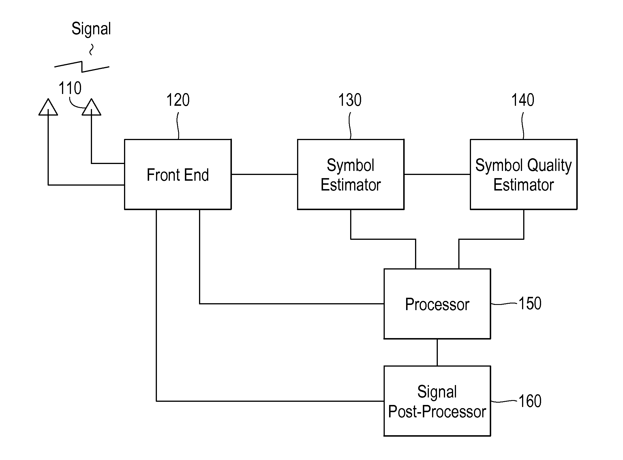
[0038]FIG. 1 shows an embodiment of the invention. The front end processor 120 receives a signal from one or more antennae (two are shown in the figure, as an example), using an RF front end 110, which performs operations such as down conversion, A / D conversion (not shown), and then the front end resolves the signal into the constituent multipaths from various sources such as base stations. As is understood in the art, a single stream of received baseband data may be composed of multiple constituent sig...


PUM


Abstract

A receiver in a CDMA system comprises a front end processor that generates a combined signal per source. A symbol estimator processes the combined signal to produce symbol estimates. An S-Matrix Generation module refines these symbol estimates based on the sub channel symbol estimates. An interference canceller is configured for cancelling interference from at least one of the plurality of received signals for producing at least one interference-cancelled signal.

Description

CROSS-REFERENCE TO RELATED APPLICATIONS [0001]This application claims priority to U.S. patent application Ser. No. 12 / 916,467, entitled “Systems and Methods for Serial Cancellation,” and filed Oct. 29, 2010; which claims priority to U.S. patent application Ser. No. 11 / 893,707, entitled “Methods for Estimation and Interference Cancellation for signal processing,” and filed Aug. 17, 2007; which claims priority to (1) U.S. Patent Application No. 60 / 838,262, entitled “Technique for estimating user and background noise powers in a code division multiple access system without signaling assistance and application of such to channel quality measurement with a linear receiver,” and filed on Aug. 17, 2006; (2) U.S. patent application Ser. No. 11 / 452,027, entitled “Iterative Interference Cancellation Using Mixed Feedback Weights and Stabilizing Step Sizes,” and filed Jun. 13, 2006, now U.S. Pat. No. 7,715,508; (3) U.S. patent application Ser. No. 11 / 432,580, entitled “Interference Cancellation...

Claims


Application Information

Patent Timeline
Patent Type & Authority Applications(United States)
IPC IPC(8): H04B1/10H04L1/02H04B1/7115
CPCH04B1/7107H04B1/71072H04B1/71075H04B1/7115H04B1/7117H04B1/7097H04J13/0048H04B15/00H04J13/00H04L43/08H04W24/08H04B2001/71077H04B2201/709718
Inventor NARAYAN, ANAND P.OLSON, ERIC S.JAIN, PRASHANTTHOMAS, JOHN K.
Owner III HLDG 1
Learn More