
METHOD AND STRUCTURE FOR FORMING HIGH-PERFOMANCE FETs WITH EMBEDDED STRESSORS

Active Publication Date: 2011-03-24
GLOBALFOUNDRIES US INC
View PDF16 Cites 67 Cited by
  • Summary
  • Abstract
  • Description
  • Claims
  • Application Information

AI Technical Summary

Benefits of technology

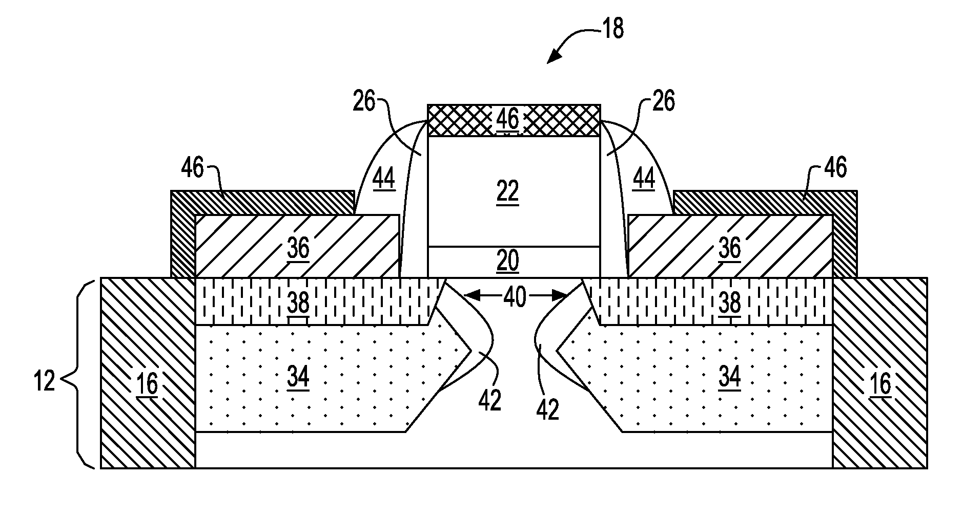
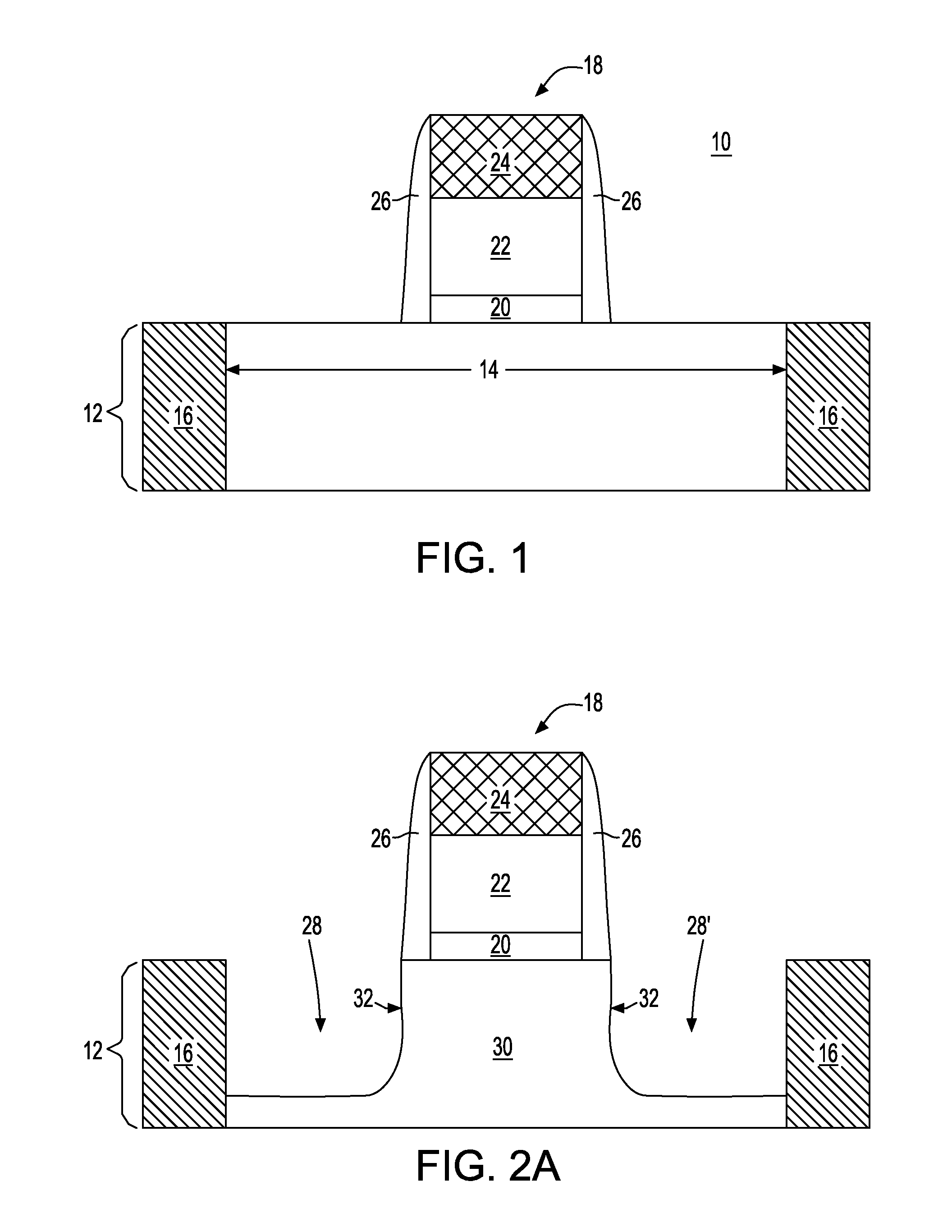
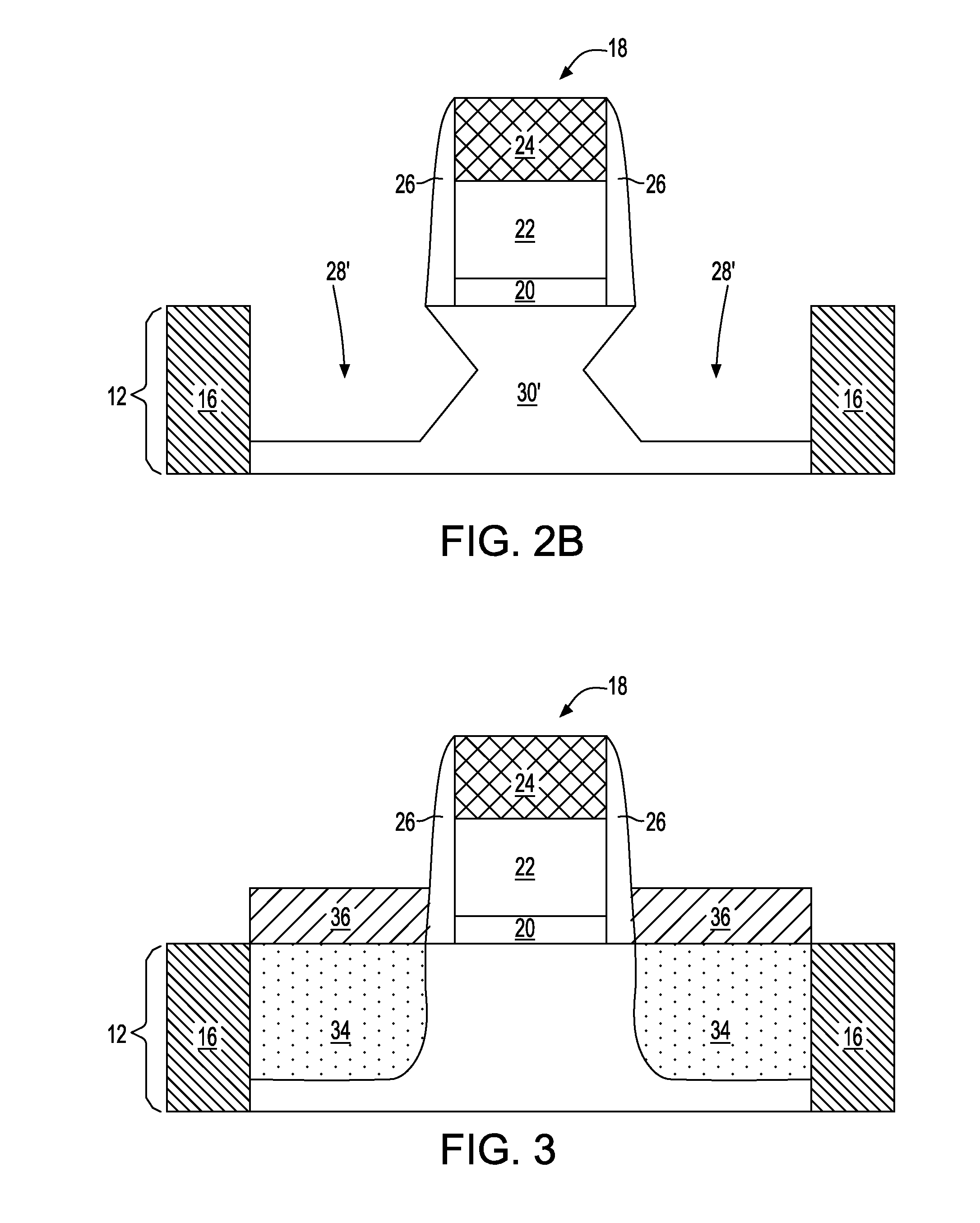
[0005]The present invention provides a high-performance semiconductor structure and a method of fabricating such a structure. The high-performance semiconductor structure includes a bi-layer embedded epitaxy semiconductor source region and drain region. The first layer of the bi-layer is an undoped or lightly doped epitaxy semiconductor material which fills a substantial portion of recessed regions that are located within a semiconductor substrate at a footprint of at least one gate stack. The first epitaxy semiconductor material produces a strain in the device channel, without degrading short channel effects. The second layer of the bi-layer is an in-situ doped epitaxy semiconductor material whose dopant concentration is substantially greater than the first epitaxy semiconductor material. The second epitaxy semiconductor material provides a dopant source for formation of an extension region with high dopant activation. Moreover, the second epitaxy semiconductor material provides superior short channel control and lowers the external resistance of the resultant structure. The high-performance semiconductor structure does not include a traditional deep and heavily doped source region and a traditional deep and heavily doped drain region. As such, the structure has better strain conservation and better short-channel control.

Problems solved by technology

While this late embedded stressor process provides stress conservation and lower source / drain resistance, the process provides a FET that exhibits poor short channel effects due to the formation of deep and heavily doped source and drain regions.
Also, this technique requires complicated first spacers, and has a compatibility issue with high k / metal gate stacks.

Method used


Image

  • METHOD AND STRUCTURE FOR FORMING HIGH-PERFOMANCE FETs WITH EMBEDDED STRESSORS
  • METHOD AND STRUCTURE FOR FORMING HIGH-PERFOMANCE FETs WITH EMBEDDED STRESSORS
  • METHOD AND STRUCTURE FOR FORMING HIGH-PERFOMANCE FETs WITH EMBEDDED STRESSORS

Examples


Embodiment Construction

[0016]In the following description, numerous specific details are set forth, such as particular structures, components, materials, dimensions, processing steps and techniques, in order to provide an understanding of some aspects of the present invention. However, it will be appreciated by one of ordinary skill in the art that the invention may be practiced without these specific details. In other instances, well-known structures or processing steps have not been described in detail in order to avoid obscuring the invention.

[0017]It will be understood that when an element as a layer, region or substrate is referred to as being “on” or “over” another element, it can be directly on the other element or intervening elements may also be present. In contrast, when an element is referred to as being “directly on” or “directly over” another element, there are no intervening elements present. It will also be understood that when an element is referred to as being “beneath” or “under” another...


PUM


Abstract

A high-performance semiconductor structure and a method of fabricating such a structure are provided. The semiconductor structure includes at least one gate stack, e.g., FET, located on an upper surface of a semiconductor substrate. The structure further includes a first epitaxy semiconductor material that induces a strain upon a channel of the at least one gate stack. The first epitaxy semiconductor material is located at a footprint of the at least one gate stack substantially within a pair of recessed regions in the substrate which are present on opposite sides of the at least one gate stack. A diffused extension region is located within an upper surface of said first epitaxy semiconductor material in each of the recessed regions. The structure further includes a second epitaxy semiconductor material located on an upper surface of the diffused extension region. The second epitaxy semiconductor material has a higher dopant concentration than the first epitaxy semiconductor material.

Description

BACKGROUND[0001]The present invention relates to a semiconductor structure and a method of fabricating the same. More particularly, the present invention relates to a high-performance semiconductor structure including a bi-layer embedded epitaxy semiconductor source region and drain region.[0002]Mechanical stresses within a semiconductor device substrate have been widely used to modulate device performance. For example, in common silicon technology, hole mobility is enhanced when the channel is under compressive stress, while the electron mobility is enhanced when the channel is under tensile stress. Therefore, compressive and / or tensile stresses can be advantageously created in the channel regions of a p-channel field effect transistor (pFET) and / or an n-channel field effect transistor (nFET) in order to enhance the performance of such devices.[0003]One possible approach for creating a desirable stressed silicon channel region is to form embedded silicon germanium (SiGe) or silicon...

Claims


Application Information

Patent Timeline
IPC IPC(8): H01L29/78H01L21/336
CPCH01L21/2257H01L21/26586H01L29/165H01L29/41775H01L29/665H01L29/7848H01L29/6656H01L29/6659H01L29/66628H01L29/66636H01L29/7834H01L29/66545H01L29/7833
Inventor CHENG, KANGGUODORIS, BRUCE B.KHAKIFIROOZ, ALISHAHIDI, GHAVAM G.
Owner GLOBALFOUNDRIES US INC
Learn More