
Wireless resource allocation apparatus and method

Inactive Publication Date: 2011-03-17
KDDI CORP
View PDF22 Cites 13 Cited by
  • Summary
  • Abstract
  • Description
  • Claims
  • Application Information

AI Technical Summary

Benefits of technology

[0011]In light of the above circumstances, an object of the present invention is to provide a wireless resource allocation apparatus and a corresponding method for more efficiently performing wireless resource allocation.
[0035]In accordance with the present invention, it is possible to more efficiently perform the wireless resource allocation.

Problems solved by technology

However, in actual VoIP traffics, especially in downstream links, each packet may not arrive at a scheduled time, due to, for example, congestion in an upper-layer network.
In such a case, it is impossible to perform efficient wireless resource allocation.

Method used


Image

  • Wireless resource allocation apparatus and method
  • Wireless resource allocation apparatus and method
  • Wireless resource allocation apparatus and method

Examples


Embodiment Construction

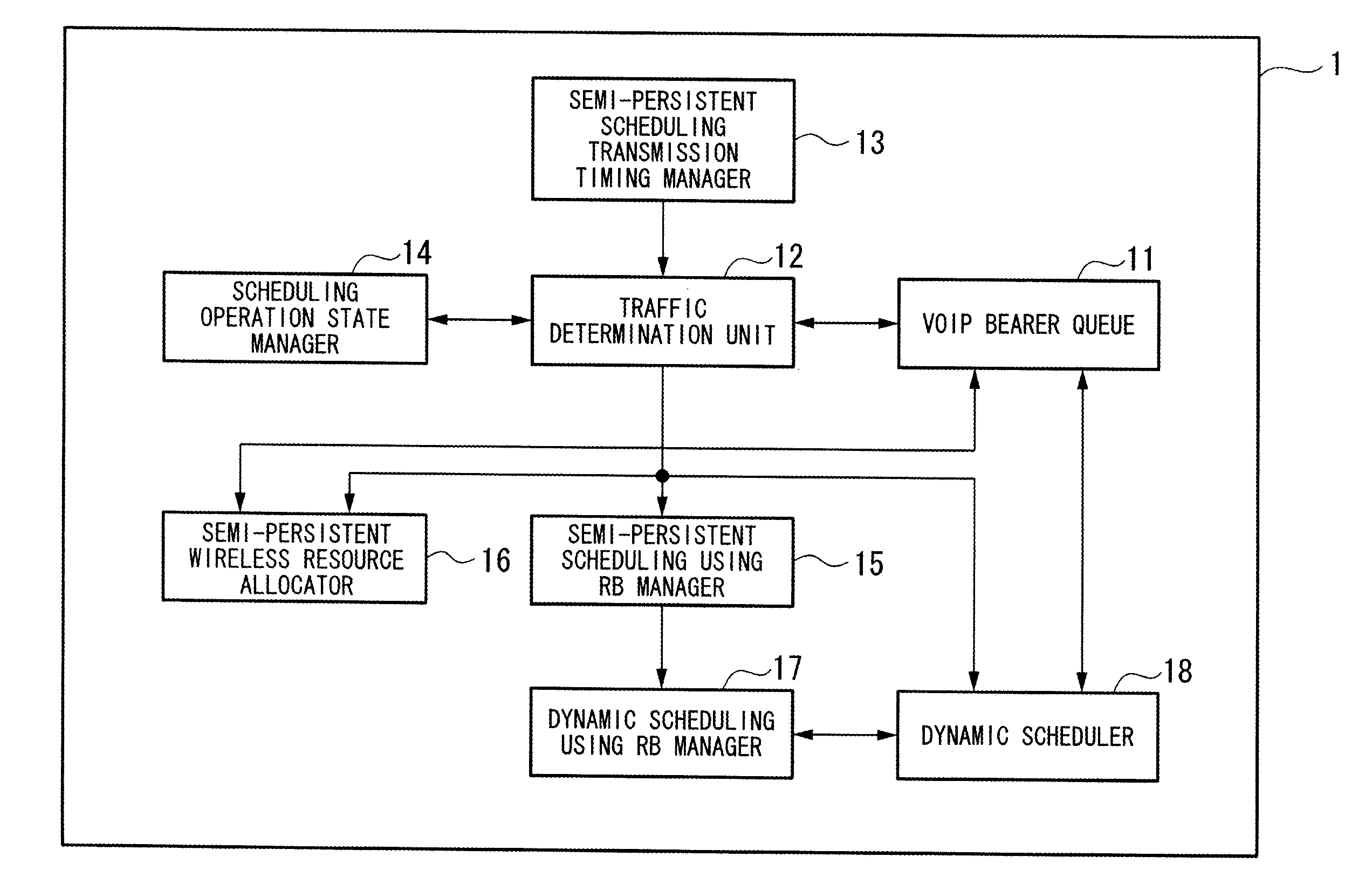
[0039]Hereinafter, an embodiment of the present invention will be described with reference to the appended figures.

[0040]FIG. 1 is a diagram showing the general structure of a network, which includes (i) a base station having a wireless resource allocation apparatus of the present embodiment and (ii) terminal stations which perform voice communication by means of VoIP.

[0041]A base station 100 and a terminal station 101 are connected via a wireless network, so that data can be transmitted and received between them. The base station 100 and the terminal station 101 use a communication standard called LTE (long term evolution).

[0042]The base station 100 is connected to a network 200, and can communicate with a terminal station 300 via the network 200.

[0043]The base station 100 receives data from the terminal station 300, and sends the received data to the terminal station 101. The base station 100 also receives data from the terminal station 101, and sends the received data to the term...


PUM


Abstract

A wireless resource allocation apparatus performs determining an amount of VoIP traffic for each terminal station; determining whether semi-persistent scheduling or dynamic scheduling is used for transmitting each packet of the VoIP traffic, based on a result of the determination for the amount of the VoIP traffic; managing, for each terminal station, a resource block allocated in the semi-persistent scheduling; and managing each resource block which is not managed for the allocation in the semi-persistent scheduling and is allocated in the dynamic scheduling. If it is determined that the dynamic scheduling is used for transmitting each packet of the VoIP traffic to a terminal station, the resource block, which has been managed for the relevant terminal station as a resource block allocated in the semi-persistent scheduling, is released, and the released resource block is managed as a resource block allocated in the dynamic scheduling.

Description

BACKGROUND OF THE INVENTION[0001]1. Field of the Invention[0002]The present invention relates to a wireless resource allocation apparatus and a corresponding method.[0003]Priority is claimed on Japanese Patent Application No. 2009-214854, filed Sep. 16, 2009, the contents of which are incorporated herein by reference.[0004]2. Description of the Related Art[0005]In recent years, LTE (long term evolution), one of 3GPP (third generation partnership project) standards, is known as an advanced mobile communication method for implementing high-speed and wide-range wireless transmission (see, for example, Non-Patent Document 1: 3GPP TS 36.211, “Evolved Universal Terrestrial Radio Access (E-UTRA); Physical channels and modulation”).[0006]In the LTE standard, an OFDMA (orthogonal frequency division multiple access) method is used as a wireless transmission method for downstream links (i.e., links from a base station to terminal stations). The OFDMA method is a multi-carrier transmission meth...

Claims


Application Information

Patent Timeline
IPC IPC(8): H04L12/24
CPCH04W24/00H04W28/06H04W88/08H04W72/1257H04W72/04H04W72/535
Inventor OHSEKI, TAKEOKOMINE, TOSHIHIKOKONISHI
Owner KDDI CORP
Learn More