
Method and a system for operating a working machine

a working machine and working system technology, applied in the field of methods for operating working machines, can solve the problems that known solutions do not utilise all the benefits, and achieve the effect of increasing the degree of modularity

Active Publication Date: 2011-03-10
VOLVO CONSTR EQUIP
View PDF12 Cites 6 Cited by
  • Summary
  • Abstract
  • Description
  • Claims
  • Application Information

AI Technical Summary

Benefits of technology

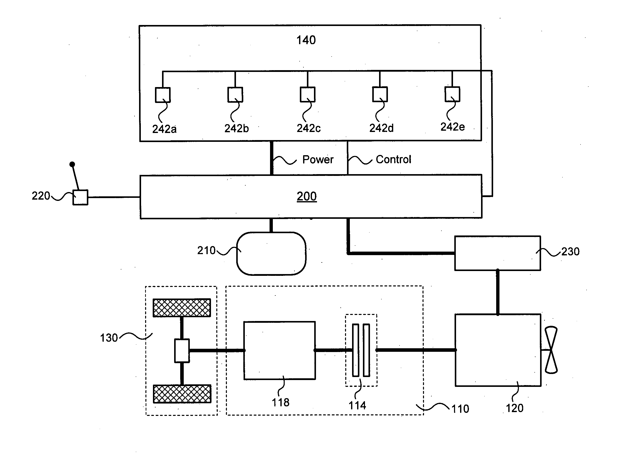
[0007]Traditionally the piston in a hydraulic working cylinder has been actuated by means of a hydraulic pump being arranged to communicate pressurised hydraulic oil in to and / or out of the working cylinder. The hydraulic pump in these traditional solutions is mechanically actuated (e.g. rotated) by the combustion engine of the wheel loader via a power outlet coupled to the combustion engine directly or coupled to the transmission line of the wheel loader. The speed of the piston is controlled indirectly via controlling the hydraulic fluid flow via proportional valves. However, in modern working machines such as wheel loaders various solutions have been proposed wherein an electrical motor is used to actuate the piston of the hydraulic working cylinder. This provides a series of advantages, e.g. a mechanical decoupling of the transmission line from the hydraulic pumps, an improved modularity and also a more flexible and precise control of the pump functionality etc.
[0009]It is desirable therefore to provide an improved modularity with respect to the units in the system utilized to control the hydraulic system of the working machine. It is also desirable to provide a relaxation or elimination of the restrictions imposed on the design of the units in the system utilized to control the hydraulic system of the working machine.

Problems solved by technology

However, known solutions do not utilise all the benefits that becomes possible when an electrical motor is used to actuate the piston of the hydraulic working cylinder.

Method used


Image

  • Method and a system for operating a working machine
  • Method and a system for operating a working machine
  • Method and a system for operating a working machine

Examples


Embodiment Construction

Structure

[0020]A Wheel Loader

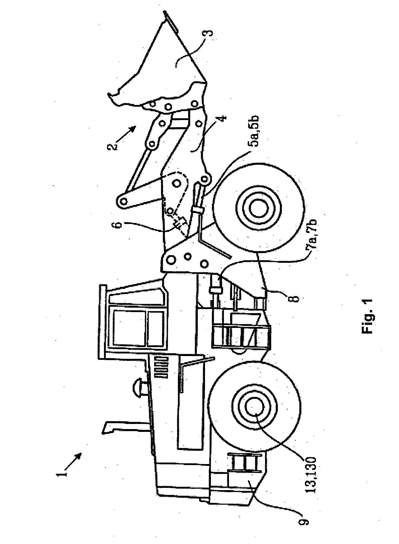
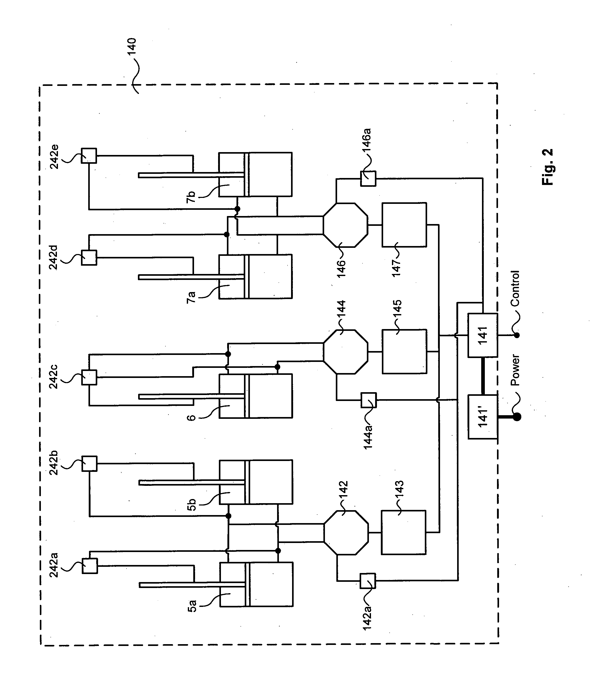
[0021]FIG. 1 is an illustration of an exemplifying wheel loader 1 having an implement 2 in the form of a bucket 3. The bucket 3 is arranged on an arm unit 4 for lifting and lowering the bucket 3. The bucket 3 can also be tilted or pivoted relative to the arm unit 4. For this purpose the wheel loader 1 is provided with a hydraulic system 140 comprising at least one hydraulic pump (not shown in FIG. 1) and working cylinders / actuators 5a, 5b, 6 for lifting and lowering of the arm unit 4, and for tilting or pivoting the bucket 3. In addition, the working hydraulic system comprises working cylinders 7a, 7b for turning the wheel loader 1 by means of relative movement of a front body 8 and a rear body 9. These features of the wheel loader 1 and variations thereof are well known to those skilled in the art and they need no detailed explanation.

[0022]A Working Hydraulic System

[0023]FIG. 2 is a schematic illustration of an exemplifying hydraulic system 140. The em...


PUM


Abstract

A method and a system for operating a working machine provided with a hydraulic system and an operator control adapted to command actuation of the hydraulic system is provided. The system includes a first control unit and a second control unit for moving an implement on the working machine and / or for steering the working machine. The method includes receiving first information regarding a status of the operator control, and determining at least one hydraulic system control information based on the first information and sending the determined hydraulic system control information to a second control unit which is adapted to control the hydraulic system accordingly.

Description

BACKGROUND AND SUMMARY[0001]The invention relates to a method for operating a working machine provided with a hydraulic system for moving an implement on the working machine and / or for steering the working machine, and an operator control means, which is adapted to command actuation of the hydraulic system. The invention is further directed to a system for performing the method.[0002]The invention is applicable on working machines within the field of industrial construction machines, in particular wheel loaders. Thus, the invention will be described with respect to a wheel loader. However, the invention is by no means limited to a particular working machine. On the contrary, the invention may be used in a plurality of heavy working machines, e.g. articulated haulers, trucks, bulldozers and excavators etc.BACKGROUND[0003]A working machine such as e.g. a wheel loader is generally provided with an internal combustion engine, a transmission line, driving wheels and a working hydraulic s...

Claims


Application Information

Patent Timeline
Patent Type & Authority Applications(United States)
IPC IPC(8): B62D6/00B62D5/06
CPCB60L2240/421B60W10/06B60W20/00B60W2510/081Y02T10/642E02F9/2075E02F9/2221E02F9/2292E02F9/2025E02F9/225Y02T10/64E02F9/2004
Inventor FILLA, RENOUNNEBACK, JOAKIMVIGHOLM, BOJOHANSSON, STEFANFROBERG, JOAKIM
Owner VOLVO CONSTR EQUIP
Learn More