
Waste Collection Device, and Waste Recycling System

a waste collection and waste technology, applied in the field of waste collection devices and waste recycling systems, can solve problems such as inability to recycle waste, and achieve the effect of preventing the deterioration of waste stock materials

Inactive Publication Date: 2011-03-10
BOROWSKI DAVID +2
View PDF24 Cites 60 Cited by
  • Summary
  • Abstract
  • Description
  • Claims
  • Application Information

AI Technical Summary

Benefits of technology

An eighteenth object of the present invention is to provide a waste recycling collection system, which affords the ability to track custody of targeted waste from the waste receptacle to the recycling process to eliminate contamination of the targeted waste being recycled in combination with the waste collection device according to the present invention.
In a preferred embodiment, multiple RF tags are associated with each plastic bag or other container to provide redundancy in the event one or more RF tags are damaged or disabled so that the plastic bag or container can still be located, for example, in the general waste stream at a waste collection center. The RF tags are relatively inexpensive, and thus economically allowing for redundancy of the RF tags in the applications of the present invention(s).
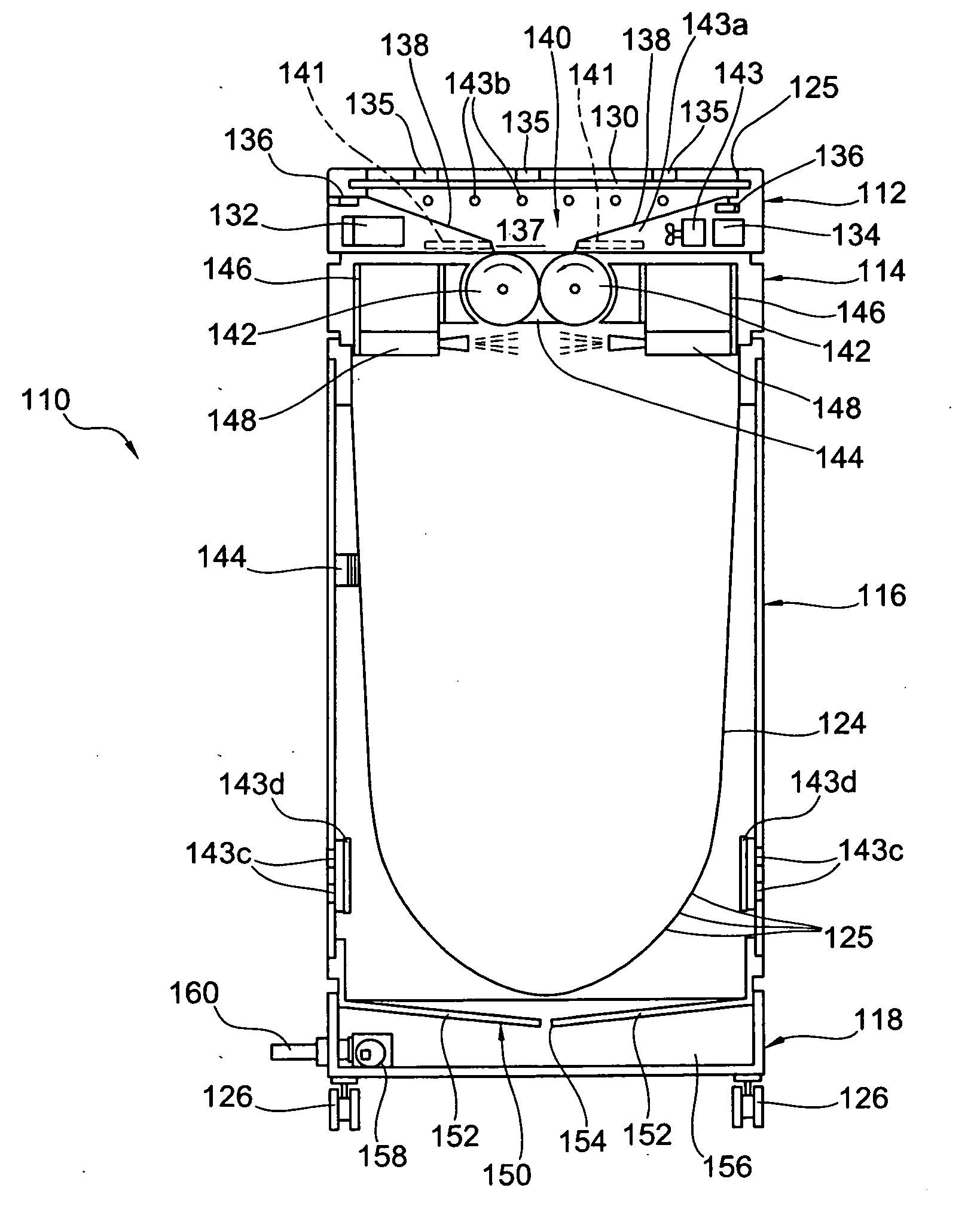
A collection vessel lower portion is located below the collection vessel housing. In a preferred embodiment, the collection vessel lower portion contains a collection pan, sump pump, drain and / or siphon to collect and eliminate the water or liquid from the waste collection device.
When the waste collection bag is filled, the waste collection bag is removed from the waste collection device. For example, a front door on the collection vessel housing is opened, and then the filled waste collection bag is removed therefrom. In a preferred embodiment, a transport bag is fitted around (i.e. nested outside) the waste collection bag just prior to removal of the waste collection bag from the collection vessel housing. The transport bag is preferably a non-perforated bag configured to contain and seal the filled waste collection bag, and prevent leaking of the waste collection bag during removal from the collection vessel housing and subsequent transport and storage thereof.
The collection bag upper portion is preferably provided with an access door through which waste can be inserted. For safety purposes, the access door is preferably an automated door having a proximity sensor to “sense” the presence of a hand as it approaches the opening to open the automated door. The shredder mechanism located below the automated door is provided with an interlock so that the shredder mechanism will not operate when the automated door is open, and will lock the automated door closed during operation of the shredder mechanism. The interlock can also include one or more proximity sensors so that the shredder mechanism will not operate if an individual or user is within a predetermined distance of the waste collection device (e.g. within several feet of the waste collection device). This provides interlock redundancy, and an additional level of safety against injury to the individual or user of the waste collection device.
The waste collection device is preferably configured to disinfect the waste, in particular disinfect the waste as it is being inserted into the waste collection device and / or when the waste is being stored inside the waste collection device. For example, the waste collection device is provided with a spray device for disbursing a liquid or powdered disinfectant onto the shredded waste. The spray device is preferably located inside the waste collection device, and configured to spray the shredded waste falling out of the shredder mechanism. Alternatively, or in addition, the spray device disburses disinfectant onto the waste sitting in the waste collection bag. For example, the waste stream is sprayed when exiting the shredder mechanism, and again sprayed at a later time when sitting in the waste storage bag. A time sequenced or programmed sequence of spraying can be configured to ensure that the waste is adequately disinfected while sitting in the waste storage bag. In operation, a waste storage bag can be replaced in minutes, hours, or even days depending on the amount of use of the particular waste collection device. Thus, timed or programmed re-treatment of the waste may be necessary to prevent deterioration of the waste stock material to allow later recycling thereof.

Problems solved by technology

This waste is transported in the dumpsters or garbage trucks to land fills, and typically not sorted before landfilling.
Once certain types of waste are mixed together, even subsequent sorting may not allow the waste to be recycled due to the contamination from the other waste.

Method used


Image

  • Waste Collection Device, and Waste Recycling System
  • Waste Collection Device, and Waste Recycling System
  • Waste Collection Device, and Waste Recycling System

Examples


Embodiment Construction

A schematic diagram of the waste recycling system 10 according to the present invention is shown in FIG. 1.

The waste recycling system begins at a store location 12. Preferably the store location 12 is just one of a series of stores of similar or dissimilar ownership that have agreed to cooperate with the desired recycling program to obtain the quantity of used waste material required for commercial recycling.

It is important to note that the preferred embodiments described in this section are directed towards particular types or otherwise targeted waste, for example, used paper cups and used plastic beverage containers. However, the system, method and device according to the present invention can have many applications for recycling different types of waste (e.g. paper plates, foam plates, plastic utensils, paper bags, paper wrappers, foam containers) and maintaining separation and custody of the waste from the point of collection to the recycling process or processing plant to avoid...


PUM


Abstract

A waste collection device configured to shred, treat waste with disinfectant, and / or remove water from the waste, and a waste recycling system.

Description

FIELD OF THE INVENTION A waste collection device, in particular a waste collection device configured for use by customers or individuals onsite in store, retail and / or office environments, and a waste recycling system. In preferred embodiments of the waste collection device, the waste collection device is configured to shred waste, disinfect waste, reduce or remove water content, liquids and / or contaminating liquids from the waste, and tag the waste for recycling purposes.BACKGROUND OF THE INVENTIONToday, most waste from stores, convenience stores, fast food chains, restaurants, retail, and office environments or locations is discarded by people or individuals (e.g. mainly customers and employees) into waste cans or waste receptacles provide onsite. These waste receptacles typically are fitted with removable plastic bags, which can be closed when filled and removed from the receptacles, and then disposed of in garbage cans or dumpsters usually located outside the buildings and adjac...

Claims


Application Information

Patent Timeline
IPC IPC(8): B65D25/16B65D30/08B65D30/00B65D25/00
CPCB65F1/0006B65F1/10B65F1/1426B65F1/1468B65F1/1484B65F1/1638B65F2210/181B65F2210/1123B65F2210/1128B65F2210/132B65F2210/137B65F2210/144B65F7/00
Inventor BOROWSKI, DAVIDHUDDLESTON, WILLIAMTHORP, BENJAMIN
Owner BOROWSKI DAVID
Learn More