
Method of designing semiconductor device

a technology of semiconductor devices and design methods, applied in the field of semiconductor device design methods, can solve the problems of gate insulating film damage, gate insulating film below the gate b>1/b> damage, time required, etc., and achieve the effect of accurate gate size and reduced ta

Inactive Publication Date: 2011-03-03
RENESAS ELECTRONICS CORP
View PDF17 Cites 1 Cited by
  • Summary
  • Abstract
  • Description
  • Claims
  • Application Information

AI Technical Summary

Benefits of technology

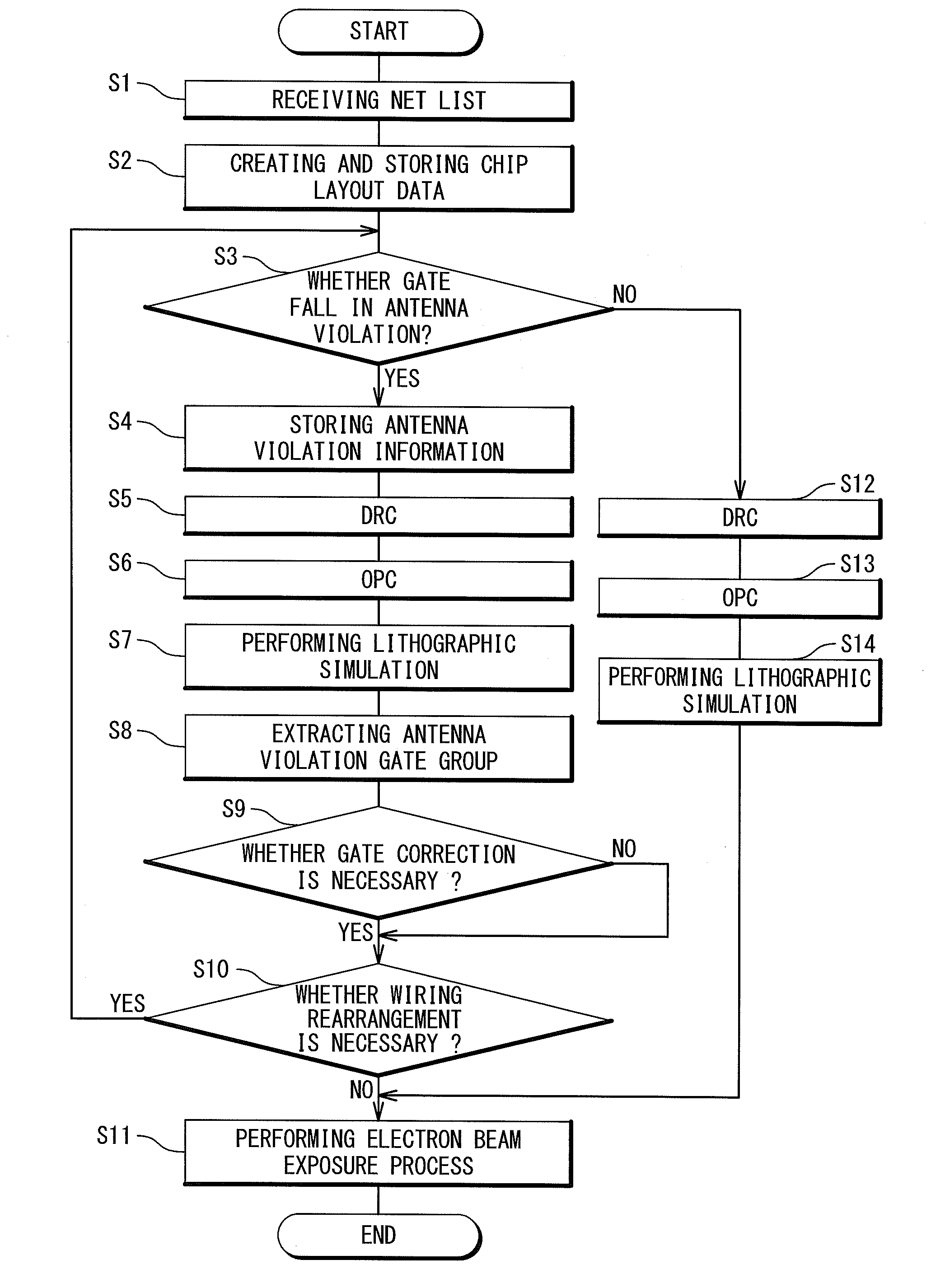
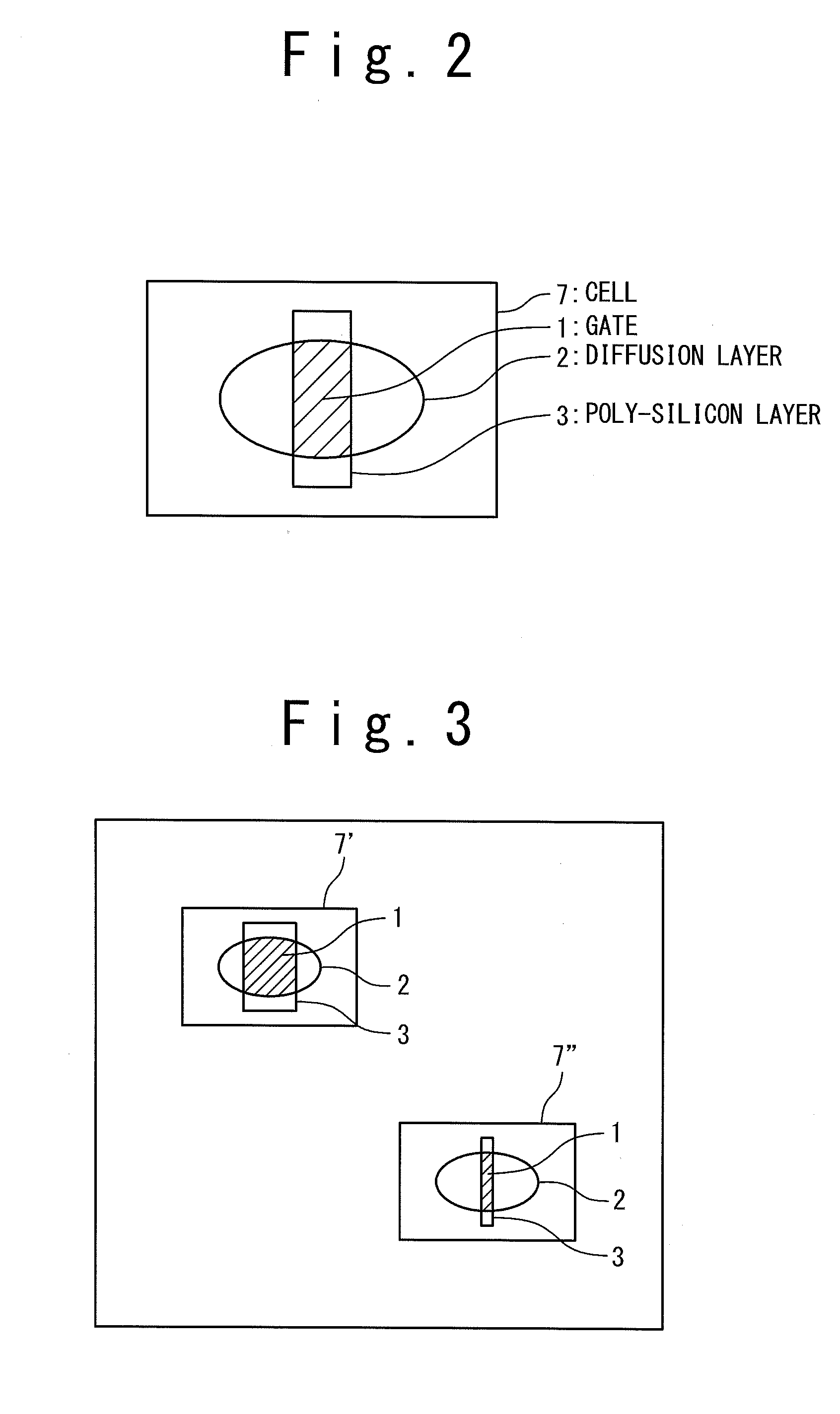
[0019]In the present invention, an accurate size of a gate can be obtained when a lithography simulation is performed. Therefore, in the case where a calculated value of each group of antenna violation gates which is included in the predicted layout data is within the range between a first setting value and a second setting value, it is not required to perform the correction (rearrangement) of the wirings connected to the group of the antenna violation gates by adjusting the size of each group of the antenna violation gates. Thus, according to the method of designing the semiconductor device of the present invention, TAT can be reduced since it is not necessary to perform the correction of the all wirings when the antenna violation is avoided.

Problems solved by technology

At that time, a gate insulating film is damaged.
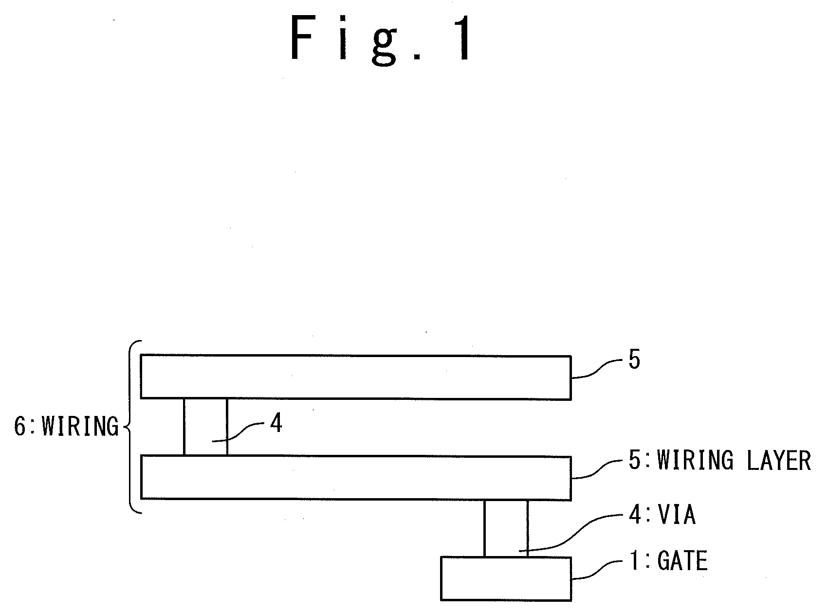
At that time, a gate insulating film below the gate 1 is damaged.
As a result, TAT (Turn Around Time; time required for a loop of a series of steps for developing and manufacturing) is extremely consumed.

Method used


Image

  • Method of designing semiconductor device
  • Method of designing semiconductor device
  • Method of designing semiconductor device

Examples


Embodiment Construction

[0030]The invention will be now described herein with reference to illustrative embodiments. Those skilled in the art will recognize that many alternative embodiments can be accomplished using the teachings of the present invention and that the invention is not limited to the embodiments illustrated for explanatory purposed.

[0031]A method for designing a semiconductor device according to an embodiment of the present invention will be described in detail below referring to the accompanying drawings.

[0032]FIG. 4 illustrates a system to which the method for designing the semiconductor device according to the embodiment of the present invention is applied. The system includes a designing device 10 and an electron beam exposure device 100. The electron beam exposure device 100 is a known exposure device and the detailed description thereof will be omitted.

[0033]The designing device 10 performs CP (Character Projection) exposure. The CP exposure is the method which was developed in order ...


PUM

PropertyMeasurementUnit
areaaaaaaaaaaa
sizeaaaaaaaaaa
area ratioaaaaaaaaaa

Abstract

This is a method of designing a semiconductor device. The method includes: arranging cells used for an electric circuit and wirings respectively connected to gates of the cells in a coordinate region to create chip layout data including the cells, gates and wirings; checking whether each gate included in the chip layout data is in antenna violation; storing antenna violation information in an error-remaining portion library, the antenna violation information representing an antenna violation gate group, in which gates in the antenna violation are contained, in the gates included in the chip layout data; performing lithography simulation for the chip layout data to create predicted layout data after photoresist exposure; selecting the antenna violation gate group from the gates included in the predicted layout data, with reference to the error-remaining library; calculating a calculated value representing a ratio of an area of an wiring of the wirings with respect to an area of a gate of the antenna violation gate group connected to the wiring, for each gate of the antenna violation group; and adjusting a size of the gate of the antenna violation gate group, when the calculated value of the antenna violation group included in the predicted layout data is in a range between a first and second setting value.

Description

INCORPORATION BY REFERENCE[0001]This application is based upon and claims the benefit of priority from Japanese patent application No. 2009-198355 filed on Aug. 28, 2009, the disclosure of which is incorporated herein in its entirety by reference.BACKGROUND OF THE INVENTION[0002]1. Field of the Invention[0003]The present invention relates to a method of designing a semiconductor device.[0004]2. Description of Related Art[0005]In manufacturing processes of a semiconductor, many processes using plasma are included. The processes such as reactive ion etching, plasma CVD, a film formation and the like are performed with a wafer placed in the plasma.[0006]However, since electric charges exist in the plasma, in these manufacturing processes, the electric charges flow into a conductive portion exposed to a wafer surface and a device is electrically charged. In the case where this conductive portion is connected to a gate electrode (hereinafter referred to as a “gate”), an electric current ...

Claims


Application Information

Patent Timeline
Patent Type & Authority Applications(United States)
IPC IPC(8): G06F17/50G03F1/36G03F1/68G03F1/70G03F1/76H01L21/027H01L21/82
CPCG06F17/5036G06F2217/12G06F17/5081G06F17/5072G06F30/398G06F30/367G06F30/392G06F2119/18Y02P90/02
Inventor KOBAYASHI, NAOHIRO
Owner RENESAS ELECTRONICS CORP
Learn More