Semiconductor device and manufacturing method thereof
a semiconductor and semiconductor technology, applied in semiconductor devices, instruments, electrical devices, etc., can solve the problems of increased power consumption, distortion of signal waveforms, delay in transmission of signals, etc., and achieve the effect of reducing parasitic capacitan
- Summary
- Abstract
- Description
- Claims
- Application Information
AI Technical Summary
Benefits of technology
Problems solved by technology
Method used
Image
Examples
embodiment 1
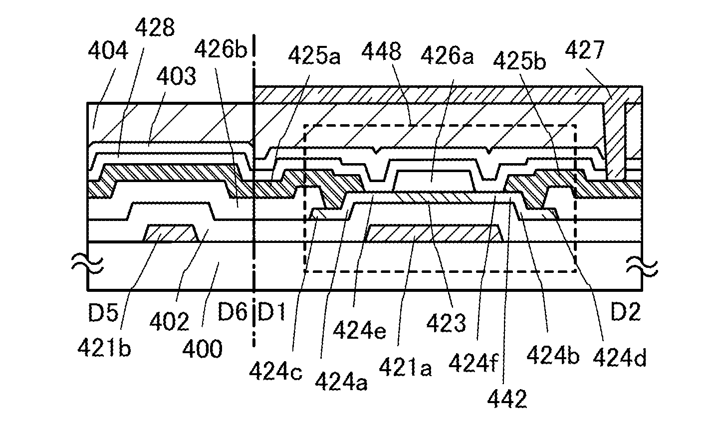
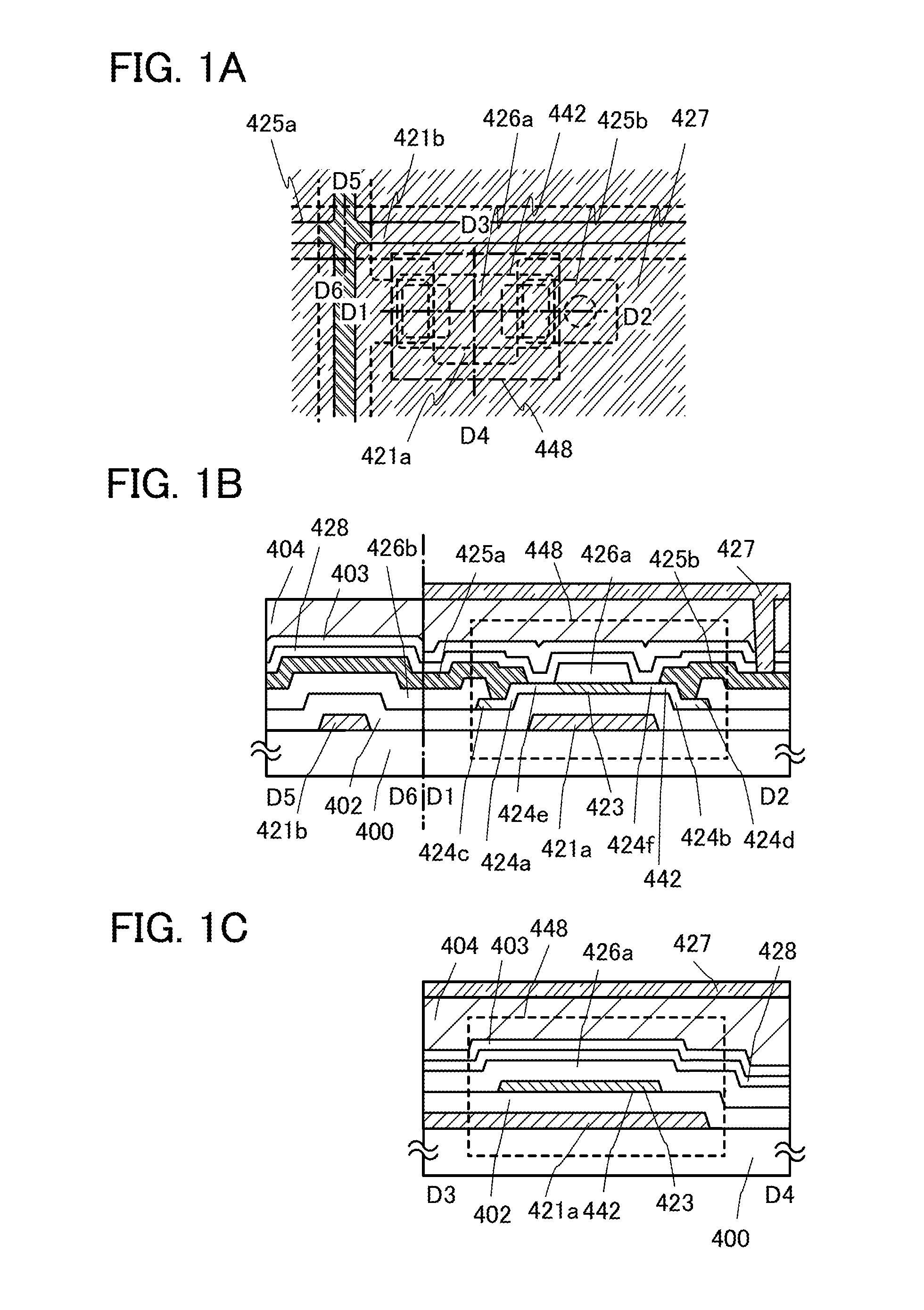
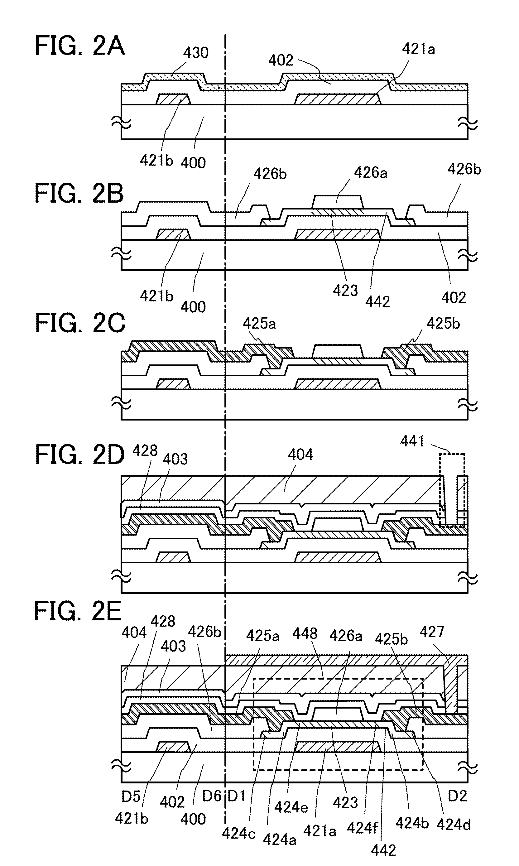
[0085]In this embodiment, one embodiment of a semiconductor device and a manufacturing method of the semiconductor device will be described with reference to FIGS. 1A to 1C and FIGS. 2A to 2E.
[0086]FIG. 1A is a top view of a channel-protection type thin film transistor 448 provided in a pixel, and FIG. 1B is a cross-sectional view taken along line D1-D2 and D5-D6 of FIG. 1A. FIG. 1C is a cross-sectional view taken along line D3-D4. Note that FIG. 2E is the same as FIG. 1B.
[0087]The thin film transistor 448 provided in the pixel is a channel-protection (also called channel-stop) type thin film transistor, which includes, over a substrate 400 having an insulating surface, a gate electrode layer 421a, a gate insulating layer 402, an oxide semiconductor layer 442 including a channel formation region 423, an oxide insulating layer 426a functioning as a channel protective layer, a source electrode layer 425a, and a drain electrode layer 425b. In addition, an insulating layer 428 is provid...
embodiment 2
[0137]In this embodiment is described an example in which an active matrix liquid crystal display device is manufactured by using the thin film transistor described in Embodiment 1 to form a pixel portion and a drive circuit over one substrate.
[0138]FIG. 3A illustrates an example of a cross-sectional structure of the active matrix substrate.
[0139]Although only the thin film transistor in the pixel portion and the wiring intersection portion are shown in Embodiment 1, the thin film transistor in the drive circuit, the storage capacitor, the gate wiring, and a terminal portion of the source wiring are shown in this embodiment, as well as the thin film transistor and the wiring intersection portion. The capacitor, the gate wiring, and the terminal portion of the source wiring can be formed by the same process as the manufacturing process described in Embodiment 1.
[0140]In FIG. 3A, a thin film transistor 220 electrically connected to a pixel electrode layer 227 is of a channel-protectio...
embodiment 3
[0168]In this embodiment, an example of a structure of a terminal portion provided over the same substrate as the thin film transistor is described. Although an example of the terminal portion of the source wiring is described in Embodiment 2, a terminal portion of the source wiring which is different from the terminal portion described in Embodiment 2 and a terminal portion of the gate wiring are shown in this embodiment. Note that in FIGS. 4A1 to 4B2, components common to FIGS. 3A and 3B keep the same reference numerals.
[0169]FIGS. 4A1 and 4A2 respectively illustrate a cross-sectional view and a top view of the terminal portion of the gate wiring. FIG. 4A1 is the cross-sectional view taken along line C1-C2 of FIG. 4A2. In FIG. 4A1, a conductive layer 225 formed over a stack of the insulating layer 216 and the protective insulating layer 203 is a terminal electrode for connection which functions as an input terminal. Furthermore, in the terminal portion of FIG. 4A1, a first termina...
PUM
 Abstract
Description
Claims
Application Information
 - R&D
- Intellectual Property
- Life Sciences
- Materials
- Tech Scout
- Unparalleled Data Quality
- Higher Quality Content
- 60% Fewer Hallucinations
Browse by: Latest US Patents, China's latest patents, Technical Efficacy Thesaurus, Application Domain, Technology Topic, Popular Technical Reports.
© 2025 PatSnap. All rights reserved.Legal|Privacy policy|Modern Slavery Act Transparency Statement|Sitemap|About US| Contact US: help@patsnap.com


