
Adhesive compositions and methods for use in failure analysis

a failure analysis and composition technology, applied in the direction of adhesive types, chemical vapor deposition coatings, ejection device structures, etc., can solve the problems of chipping or cracking of die-attaching materials, non-flexible and brittle conventional adhesive and encapsulant materials, and poor adhesion of micro-fluid ejection heads and the ejection device structure, so as to improve flow resistance and adhesion, and facilitate the identification of adhesives

Inactive Publication Date: 2011-01-20
LEXMARK INT INC
View PDF26 Cites 17 Cited by
  • Summary
  • Abstract
  • Description
  • Claims
  • Application Information

AI Technical Summary

Benefits of technology

[0015]The present invention meets this need by providing a die attach adhesive formulation that not only has better flow resistance and adhesion by the addition of an amine curative, but allows for the easier identification of the adhesive without use of expensive analytical methods by the addition of a fluorescent dye. The addition of fluorescent dye enables identification of the adhesive in ink flow paths from material flow during the cure process and other process dispense issues.

Problems solved by technology

However, the micro-fluid ejection head and the ejection device structure typically have dissimilar coefficients of thermal expansion.
In the prior art, conventional adhesive and encapsulant materials tended to be non-flexible and brittle after curing due to high temperatures required for curing and the relatively high shear modulus exhibited by the adhesive materials upon curing.
Such properties may cause the die attach materials to chip or crack.
It may also cause the components (e.g., micro-fluid ejection head and / or ejection device structure) to bow, chip, crack, or otherwise separate from one another, or to be less resilient to external forces (e.g. chips may be more prone to crack when dropped.)
Upon cooling the device structure, the device structure contracts and, with a rigid cured diebond material, high stress may be induced onto the ejection head structure to cause the aforementioned bowing, chipping, cracking, separating, etc.
Such adverse effects as bowing, chipping, cracking, separating, etc., may be even more pronounced as the substrates for the device structure are made thinner.
Among other problems, such events may result in fluid leaking, corrosion of electrical components, and poor adhesion as was as malfunctioning of the micro-fluid ejection heads, such as misdirected nozzles.
It is difficult to determine visually and analytically the differences between the different epoxy materials.
Clogged printhead nozzles could result if any of the epoxy materials are dispensed or processed incorrectly.
This results in a blockage that does not allow ink to flow out of the printhead nozzles.
This drop in viscosity during thermal cure leads to the undesirable wicking of the adhesive materials up the via wall.
It can take significant time for an analytical analysis to determine whether or not the ink flow issue is caused by a die attach wicking issue which would result in reformulation of the die attach material.

Method used


Image

  • Adhesive compositions and methods for use in failure analysis
  • Adhesive compositions and methods for use in failure analysis
  • Adhesive compositions and methods for use in failure analysis

Examples


Embodiment Construction

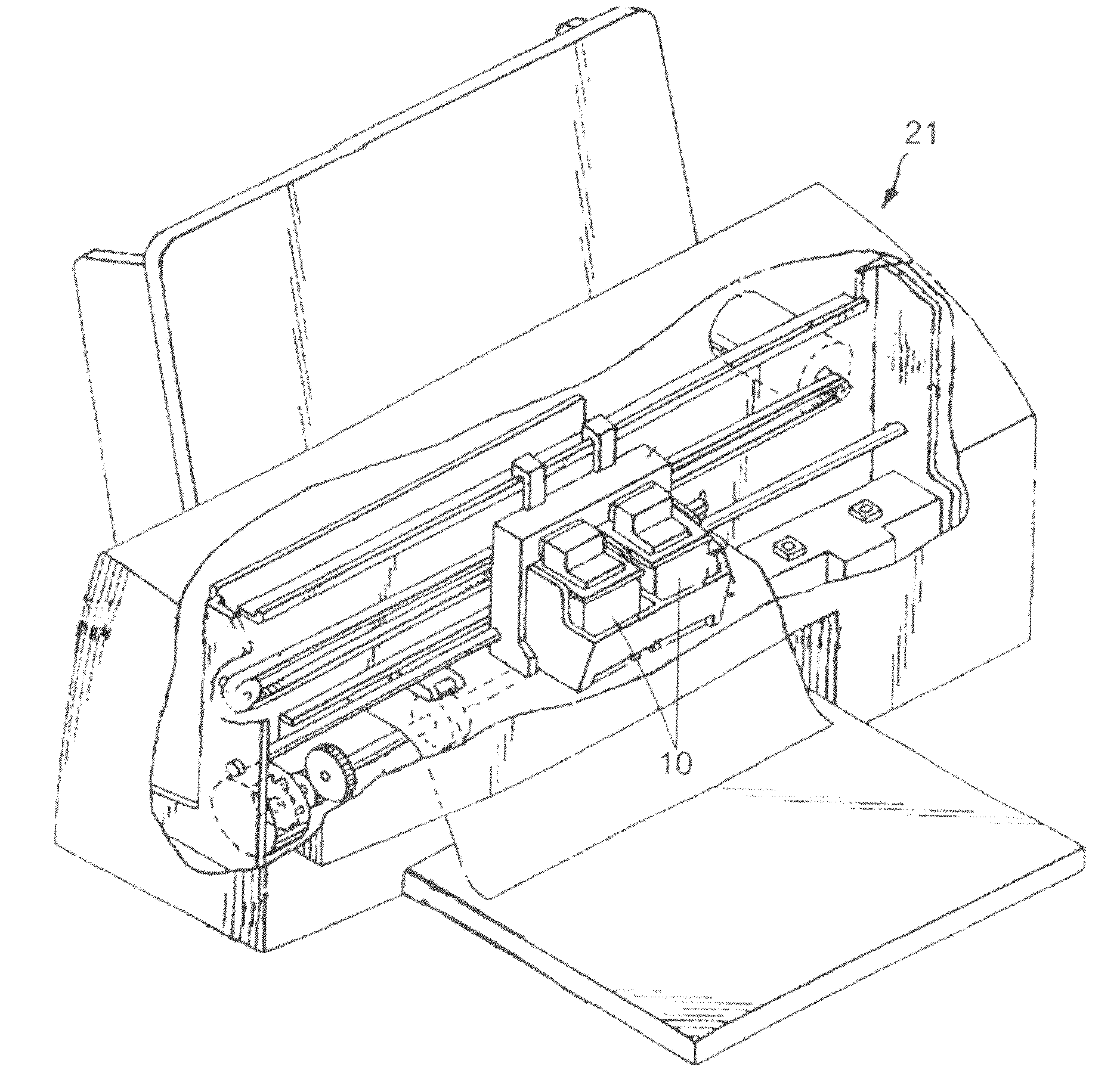
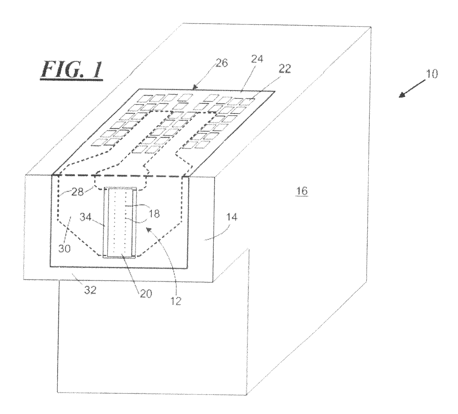
[0024]In order to more fully disclose the various embodiments of the invention, attention is directed to the following description of a representative micro-fluid ejection device incorporating the improved thermally curable adhesive described herein. With reference to FIG. 1, there is shown, in perspective view, a micro-fluid ejection device 10 including one or more micro-fluid ejection heads 12 attached to a head portion 14 of the device 10. A fluid reservoir 16 containing one or more fluids is fixedly (or removably) attached to the head portion 14 for feeding fluid to the one or more micro-fluid ejection heads 12 for ejection of fluid toward a media or substrate from nozzles 18 on a nozzle plate 20. Although FIG. 1 illustrates the fluid reservoir being directly attached to a head portion 14, other embodiments might attach a fluid reservoir indirectly to a head portion, such as by tubing, for example. Each reservoir 16 may contain a single fluid, such as black, cyan, magenta or yel...


PUM

PropertyMeasurementUnit
wavelengthsaaaaaaaaaa
shear modulusaaaaaaaaaa

Abstract

Thermally curable adhesive compositions and method for failure analysis in micro-fluid ejections heads. The adhesive composition may be provided by a composition including from about 50.0 to about 95.0 percent by weight of at least one cross-linkable resin, from about 0.1 to about 30.0 percent by weight of at least one thermal curative agent, and from about 0.0 to about 5.0 percent by weight filler, from about 0.1 to about 10.0 percent by weight fluorescent pigment. Upon curing, the adhesive composition exhibits a relatively low shear modulus.

Description

CROSS REFERENCES TO RELATED APPLICATIONS[0001]None.BACKGROUND[0002]1. Field of the Invention[0003]The present invention relates generally to adhesive compositions and, more particularly, to flexible compounds that can be cured for use as adhesives in micro-fluid ejection devices and used to improve failure analysis.[0004]2. Description of the Related Art[0005]Micro-fluid ejection heads are useful for ejecting a variety of fluids including inks, cooling fluids, pharmaceuticals, lubricants and the like. A widely used micro-fluid ejection head is an inkjet print head used in an ink printer. Ink jet printers continue to be improved as the technology for making their micro-fluid ejection heads continues to advance.[0006]In the production of conventional thermal ink jet print cartridges for use in ink jet printers, one or more micro-fluid ejection heads are typically bonded to one or more chip pockets of an ejection device structure. A micro-fluid ejection head typically includes a fluid-...

Claims


Application Information

Patent Timeline
Patent Type & Authority Applications(United States)
IPC IPC(8): C23C16/52C09J163/00C09J183/00C09J175/04C09J11/00
CPCC09J163/00
Inventor GRAHAM, DAVID CHRISTOPHERHOLT, JR., GARY ANTHONYPROVENCE, JOEL PAULWEAVER, SEAN TERRENCEWELLS, RICHARD DONOVAN
Owner LEXMARK INT INC
Learn More