
Remote Hydrogen Plasma With Ion Filter for Terminating Silicon Dangling Bonds

a technology of ion filter and hydrogen plasma, which is applied in the direction of electric discharge tubes, basic electric elements, electric discharge tubes, etc., can solve the problems of poor doping ability of amorphous si:h (a-si:h), adverse effects of doping on a-si:h layer quality, and inability to manufacture p-n-type diodes for solar cells

Inactive Publication Date: 2011-01-13
APPLIED MATERIALS INC
View PDF6 Cites 425 Cited by
  • Summary
  • Abstract
  • Description
  • Claims
  • Application Information

AI Technical Summary

Benefits of technology

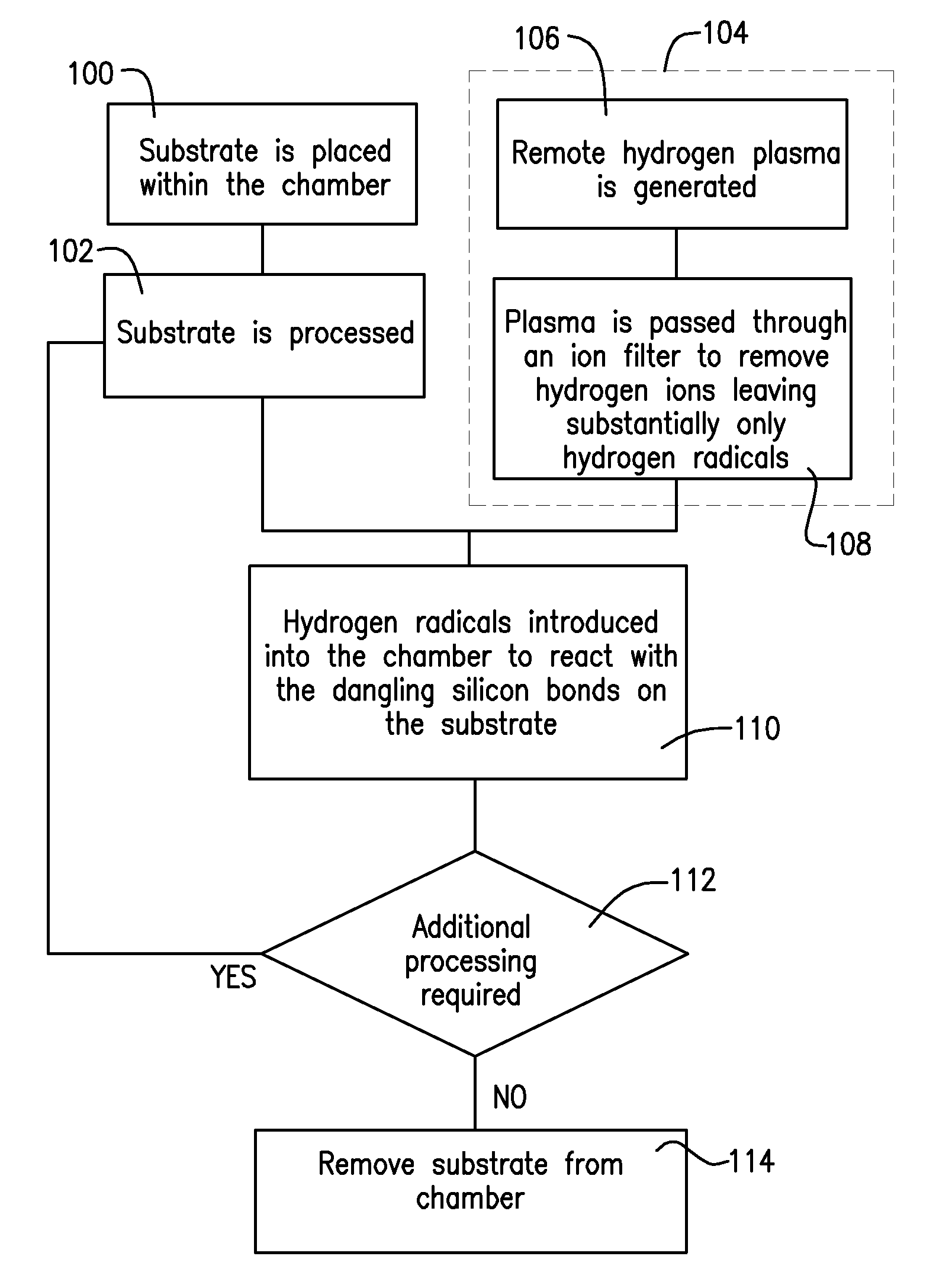
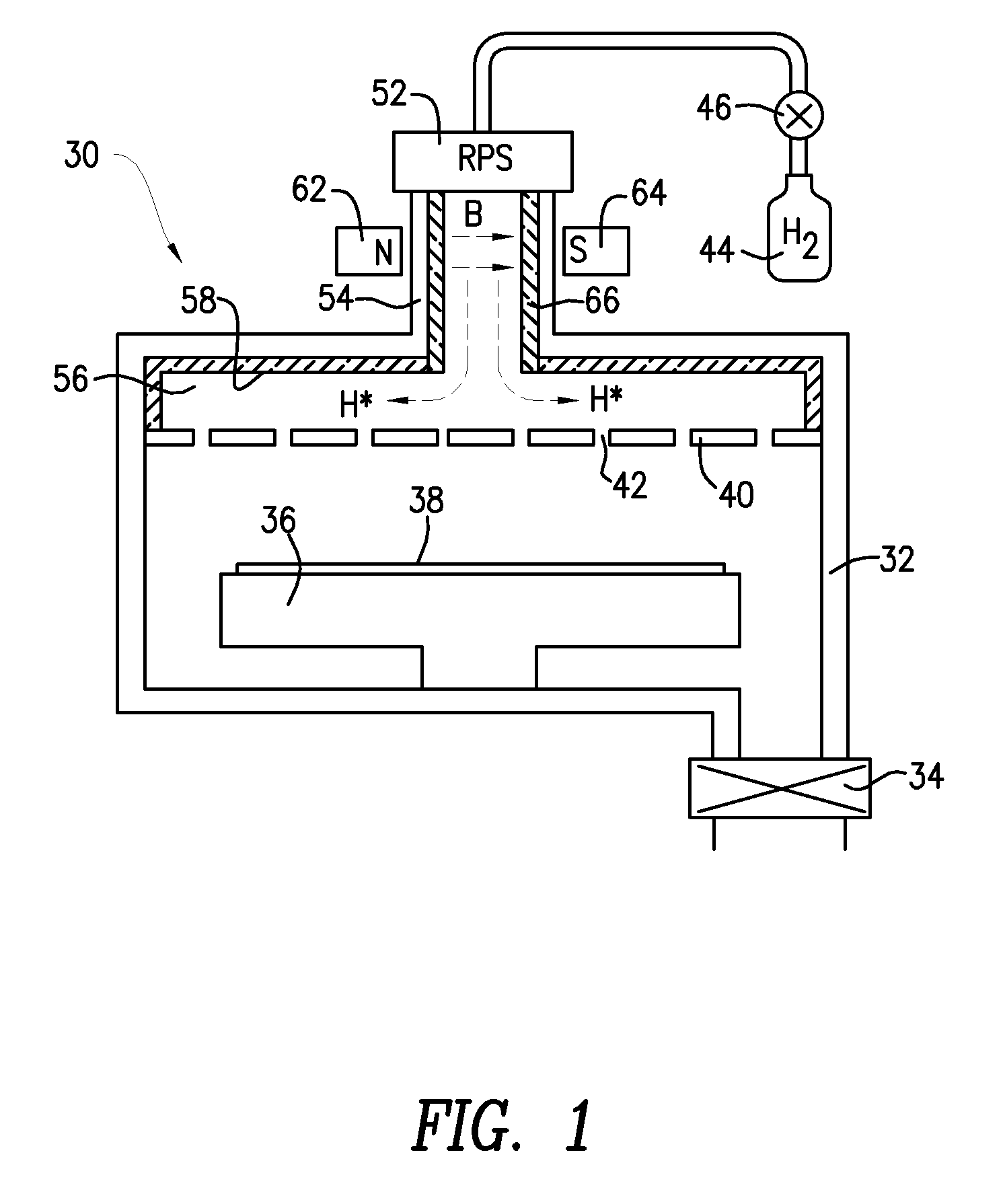
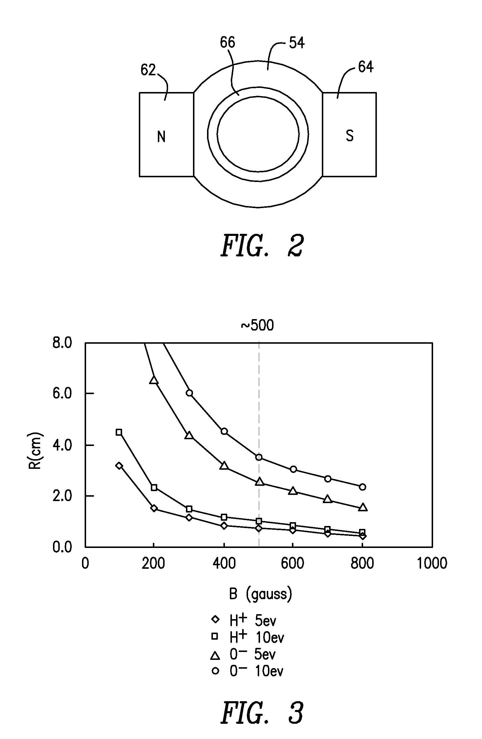
[0013]In one or more embodiments, the hydrogen radicals in the hydrogen plasma, which have passed through the ion filter, have an energy level that has been reduced to prevent damage to the silicon layer.
[0016]In one or more embodiments, the silicon layer is a p-type or n-type silicon which has been deposited onto a transparent conductive oxide layer on a silicon substrate. The silicon layer of specific embodiments is part of a photovoltaic cell and the energy of the hydrogen radicals is such that they cause substantially no damage to the transparent conductive oxide layer.

Problems solved by technology

It is well known that p-n type diodes are not feasible for solar cells due to the following factors: (1) the doping capability of amorphous Si:H (a-Si:H) is rather poor; (2) doping has a detrimental effect on a-Si:H layer quality because the dopants lead to the creation of many additional Si dangling bonds, which are the main recombination centers in this material; and (3) in a classical p-n type diode, carrier collection is obtained by minority carrier diffusion within p- and n-type layers.
In solar cell production, the thermal budget is quite limited due to many concerns.
Then, the highest temperature one can use for any process after the silicon deposition is less than 200° C. At this temperature, the forming gas anneal will not effectively passivate the silicon dangling bonds in PECVD formed films.
However, if in-situ low temperature (e.g., 200° C.) hydrogen plasma is applied, hydrogen ions could have high energy and large energy dispersion.
These H+ ions could have major detrimental impacts on the transparent conductive oxide (TCO) film (e.g., indium oxide and tin oxide) which is deposited prior to the silicon film deposition.

Method used


Image

  • Remote Hydrogen Plasma With Ion Filter for Terminating Silicon Dangling Bonds
  • Remote Hydrogen Plasma With Ion Filter for Terminating Silicon Dangling Bonds
  • Remote Hydrogen Plasma With Ion Filter for Terminating Silicon Dangling Bonds

Examples


Embodiment Construction

[0030]Before describing several exemplary embodiments of the invention, it is to be understood that the invention is not limited to the details of construction or process steps set forth in the following description. The invention is capable of other embodiments and of being practiced or being carried out in various ways.

[0031]As used in this specification and the appended claims, the singular forms “a”, “an” and “the” include plural referents unless the context clearly indicates otherwise. For example, reference to a “superstrate” may also refer to more than one superstrate, and the like.

[0032]According to an embodiment of the invention, a practical and effective way to greatly improve the efficiency of generating ion-free H radicals and the H radicals to passivate silicon dangling bonds is provided. In one embodiment, a remote hydrogen plasma source with an ion filter (e.g., RPS system on top of a PECVD chamber) can be employed. The hydrogen radicals (without ions) can be introduc...


PUM


Abstract

Apparatus and methods for repairing silicon dangling bonds resulting from semiconductor processing are disclosed. The silicon dangling bonds can be repaired by introducing hydrogen radicals with substantially no hydrogen ions into the processing chamber to react with the silicon dangling bonds, eliminating them.

Description

CROSS REFERENCE TO RELATED APPLICATIONS[0001]This application claims the benefit of priority under 35 U.S.C. §119(e) to U.S. Provisional Patent Application No. 61 / 170,838, filed Apr. 20, 2009, which is hereby incorporated by reference in its entirety.BACKGROUND[0002]Embodiments of the present invention generally relate to methods and apparatus for semiconductor processing. Specific embodiments pertain to methods and apparatus to minimize or eliminate dangling silicon bonds during semiconductor processing.[0003]It is well known that p-n type diodes are not feasible for solar cells due to the following factors: (1) the doping capability of amorphous Si:H (a-Si:H) is rather poor; (2) doping has a detrimental effect on a-Si:H layer quality because the dopants lead to the creation of many additional Si dangling bonds, which are the main recombination centers in this material; and (3) in a classical p-n type diode, carrier collection is obtained by minority carrier diffusion within p- and...

Claims


Application Information

Patent Timeline
IPC IPC(8): H01L21/30
CPCH01J37/32357H01L21/3003H01L21/3105H01L21/321H01L21/425H01L31/03685Y02E10/548H01L31/075H01L31/1824H01L31/1868H01L31/202Y02E10/545H01L31/03762Y02P70/50
Inventor XU, ZHI
Owner APPLIED MATERIALS INC
Learn More