
Friction-stir Weld-tool and Method

a technology of friction-stir and weld tool, which is applied in the direction of manufacturing tools, soldering devices,auxillary welding devices, etc., can solve the problems of high labor costs for preparing and welding all of the tube joints, thwarting commercialization, and contributing to the capital cost of the otec plan

Active Publication Date: 2011-01-06
LOCKHEED MARTIN CORP
View PDF5 Cites 47 Cited by
  • Summary
  • Abstract
  • Description
  • Claims
  • Application Information

AI Technical Summary

Benefits of technology

[0017]In some embodiments, the anvil is provided as a plug that is forced into the open end of section of the tube to be welded to the tube plate. During a subsequent welding process, a weld-tool is moved around the circumference of the tube, outside the area of the plug, to plasticize the tube wall and the region of the tube plate that immediately surrounds the tube wall. The plug provides a physical barrier that keeps the plasticized material from flowing out of the weld region.

Problems solved by technology

OTEC systems have been shown to be technically viable, but the high capital cost of these systems has thwarted commercialization.
The heat exchangers are the second largest contributor to OTEC plant capital cost (the largest is the cost of the offshore moored vessel or platform).
The process of welding the heat exchanger tubes has many drawbacks including: (1) high labor costs to prepare and weld all of the tube joints via manual fusion welding techniques, (2) defect repair costs due to the complex manual or semi-automatic fusion welding process, and (3) increased corrosion susceptibility due to dissimilar materials included in the fusion-weld.
For OTEC systems, in particular, galvanic-corrosion is a major cause of working fluid contamination due to the exposure of the welds to seawater.
Unfortunately, it was concluded that fabricating shell-and-tube heat exchangers of sufficient surface area out of aluminum would be prohibitively expensive.
Corrosion and biofouling issues, however, continue to plague heat exchanges based on roll-bond panels.
During the first year of testing, serious ammonia leaks were experienced due to corrosion.
The corrosion was due to electrolysis, which was caused by the spacer material between the aluminum panels.
Remaining hurdles for compact aluminum heat exchangers at that time included concerns over the placement of brazed sections within a heat exchanger core.
Such systems, however, will require a very high volume of seawater flow.
Unfortunately, development of a shell-and-tube heat exchanger, suitable for OTEC applications, that accommodates high flow rates while minimizing pumping parasitic losses and offering long life in the ocean environment remains elusive.

Method used


Image

  • Friction-stir Weld-tool and Method
  • Friction-stir Weld-tool and Method
  • Friction-stir Weld-tool and Method

Examples


Embodiment Construction

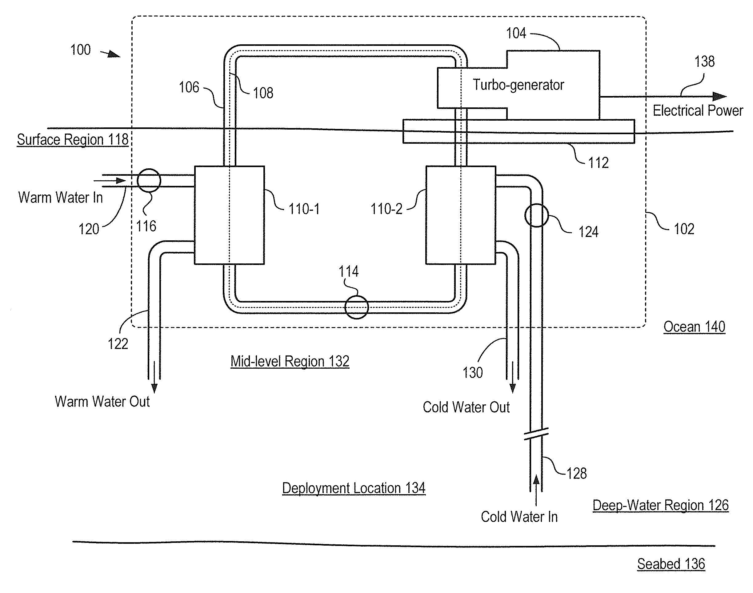
[0034]FIG. 1 depicts a schematic diagram of an OTEC power generation system in accordance with an illustrative embodiment of the present invention. OTEC system 100 comprises offshore platform 102, turbogenerator 104, closed-loop conduit 106, evaporator 110-1, condenser 110-2, hull 112, pumps 114, 116, and 124, and conduits 120, 122, 128, and 130.

[0035]Offshore platform 102 is a tension leg offshore platform comprising buoyant hull 112, which includes a deck, caissons, and pontoons. The hull is supported above seabed 136 by rigid tension legs that are anchored to seabed 136 at deployment location 134. For clarity, the deck, caisson, pontoons, and tension legs are not shown in FIG. 1.

[0036]In some embodiments, offshore platform 102 is deployed at a deployment location in a body of water other than an ocean (e.g., a lake, sea, etc.). In some embodiments, offshore platform 102 is an offshore platform other than a tension leg offshore platform, such as a semi-submersible, spar, drill shi...


PUM

PropertyMeasurementUnit
Diameteraaaaaaaaaa
Transport propertiesaaaaaaaaaa

Abstract

A method for joining a tube and tube plate for use in a tube-and-shell heat exchanger is disclosed. The method enables a joint between the tube and tube plate that is substantially hermetic and substantially corrosion-resistant. The method comprises providing an anvil inside the tube, wherein the anvil supports the tube wall during a friction-stir welding process used to join the tube and tube plate. The anvil facilitates formation of a reliable weld region and enables faster friction-stir welding.

Description

CROSS REFERENCE TO RELATED APPLICATIONS[0001]This case claims priority of U.S. Provisional Patent Application Ser. No. 61 / 222,438, which was filed Jul. 1, 2009 (Attorney Docket: 083874-0138), and which is incorporated herein by reference.[0002]If there are any contradictions or inconsistencies in language between this application and one or more of the cases that have been incorporated by reference that might affect the interpretation of the claims in this case, the claims in this case should be interpreted to be consistent with the language in this case.FIELD OF THE INVENTION [0003]The present invention relates to tube-and-shell heat exchangers in general, and, more particularly, to methods for fabricating tube-and-shell heat exchangers.BACKGROUND OF THE INVENTION[0004]Ocean thermal energy conversion (“OTEC”) is a method for generating electricity based on the temperature difference that exists between deep and shallow waters of a large body of water, such as an ocean, sea, gulf, o...

Claims


Application Information

Patent Timeline
IPC IPC(8): B23K20/12B23K31/02
CPCB23K20/122B23K20/1265Y02E10/34B23K2201/14B23K20/129B29L2031/18B29C65/0681B29C66/112B29C66/114B29C66/53465B29C66/81433B29C66/8322B29C66/836B23K2101/14Y02E10/30
Inventor TAKESHITA, RIKI P.BROWN, RANDY J.ELLER, MICHAEL R.PHAM, DUY N.
Owner LOCKHEED MARTIN CORP
Learn More