Cable End Anchorage With Overload Protection

a technology of overload protection and cable end, which is applied in the direction of cables for vehicles/pulleys, structural elements, building components, etc., can solve the problems of increased construction cost and high construction complexity, and achieve the effect of reliably decoupling the supporting structure from the maximum load and high degree of inherent rigidity and resistan

Inactive Publication Date: 2011-01-06
JOSEF GARTNER & CO
View PDF46 Cites 11 Cited by
  • Summary
  • Abstract
  • Description
  • Claims
  • Application Information

AI Technical Summary

Benefits of technology

[0007]Starting from this state of the art, it is an object of the present invention to realize cable constructions, particularly for facade construction, that feature a high degree of inherent rigidity and resistance and, on the other hand, reliably decouple the supporting structure from the maximum loads destroying the same.

Problems solved by technology

This aspect gives rise to high constructional complexity and increased costs.

Method used


Image

  • Cable End Anchorage With Overload Protection
  • Cable End Anchorage With Overload Protection
  • Cable End Anchorage With Overload Protection

Examples


Embodiment Construction

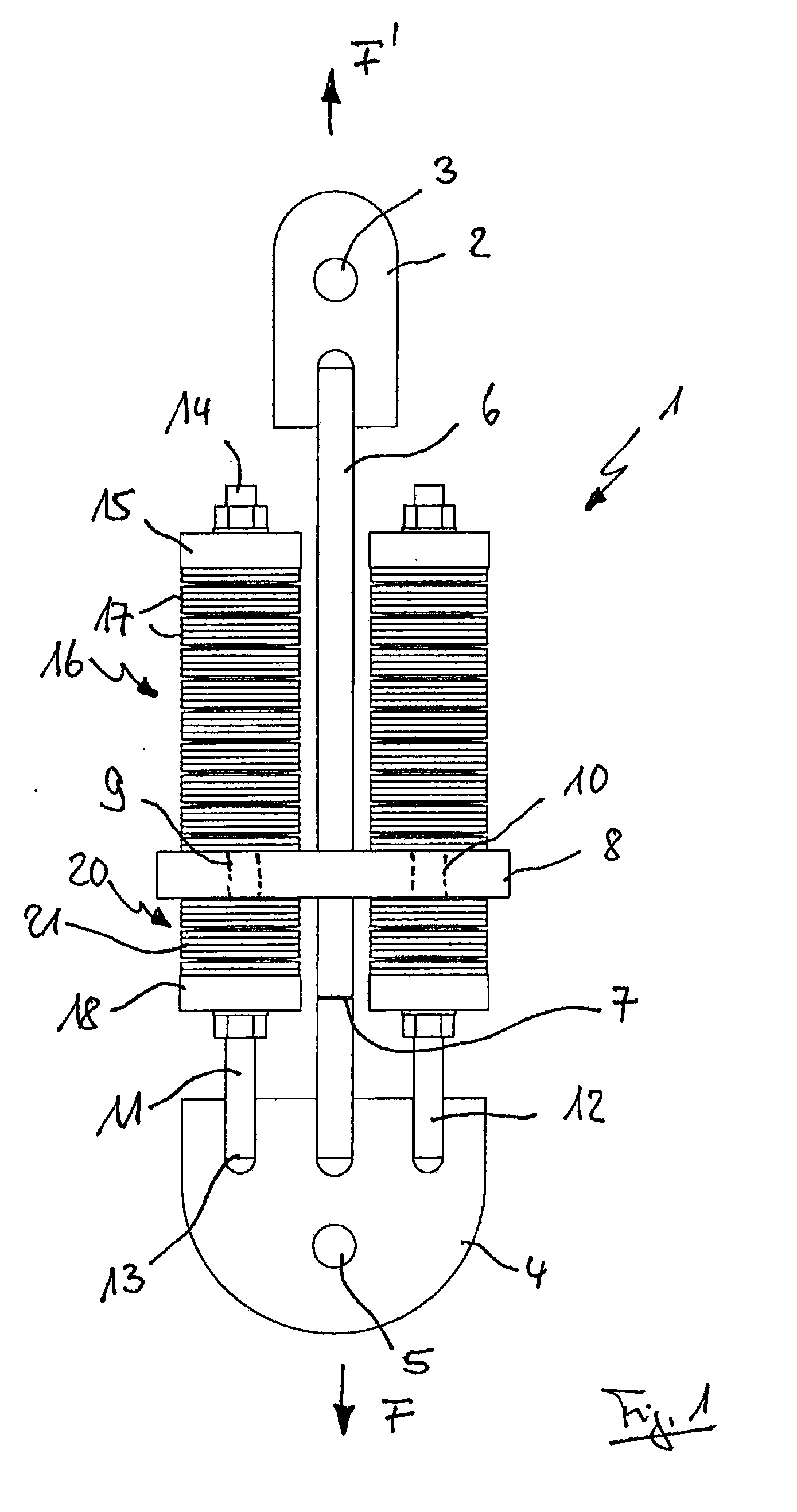
[0031]FIG. 1 illustrates a first exemplary embodiment of an inventive cable end anchorage 1. The cable end anchorage here features a first connecting element 2 in the form of a fastening plate. The fastening plate is equipped with a recess 3 for penetration of a fastening bolt (not shown) for fastening at a supporting structure (not shown). Moreover, the cable end anchorage features a second connecting element 4 equally in the form of a fastening plate with a recess 5 functionally corresponding to the recess 3. Via the recess, the end of a steel cable equipped with a corresponding fitting can be coupled with the aid of a stud bolt or the like.

[0032]The two connecting elements 2 and 4 are connected with one another in a force-transmitting manner via a bar-shaped coupling element 6, i.e. firstly in a substantially rigid fashion. When a tensile force is exerted in the direction of arrow F, in this process, the load applied at the cable is transmitted to the supporting structure.

[0033]T...


PUM


Abstract

A cable end anchorage for fastening at least one cable at a supporting structure includes at least one first connecting element for connection with the supporting structure, at least one second connecting element for connection with the cable and at least one coupling element for connection of the two connecting elements in a force-transmitting manner. In the region of the coupling element, an overload device designed as a predetermined breaking point of the coupling element is provided for unfastening the connection between the two connecting elements when a critical load has been exceeded. A stop device is provided for limiting the relative motion of the connecting elements after unfastening of the connection when a critical load has been exceeded. The cable end anchorage features a transverse plate that is connected with the coupling element in a force-transmitting manner and at least one tension rod that penetrates the transverse plate in a recess with an at least slightly radial clearance, wherein one end of the tension rod is connected with one of the two connecting elements in a force-transmitting manner on one side of the transverse plate, and a terminal plate is provided at the opposite end of the tension rod on the other side of the transverse plate, the terminal plate serving as a stop on the transverse plate when a critical load has been exceeded.

Description

[0001]This application claims priority to German Patent Application No. 10 2009 033 032.1, filed Jul. 2, 2009, and European Patent Application No. 10 167 919.9 filed Jun. 30, 2010, both of which are fully incorporated herein by reference.STATEMENT CONCERNING FEDERALLY SPONSORED RESEARCH OR DEVELOPMENT[0002]Not Applicable.FIELD OF THE INVENTION[0003]The present invention relates to a cable end anchorage for fastening at least one cable at a supporting structure, with at least one first connecting element for connection with the supporting structure, at least one second connecting element for connection with the cable and at least one coupling element for connection of the two connecting elements in a force-transmitting manner.BACKGROUND OF THE INVENTION[0004]In particular in structural engineering, here in turn especially in facade engineering, tension cable elements are frequently employed. In this context, tension cable elements feature a cable and cable end anchorages with the aid...

Claims


Application Information

Patent Timeline
Patent Type & Authority Applications(United States)
IPC IPC(8): F16G11/03
CPCE04B1/98Y10S248/909F16G11/06E04B2/885F16B2200/63
Inventor WELLERSHOFF, FRANK
Owner JOSEF GARTNER & CO
Why Eureka
Try Eureka