Cargo restraint method and system with enhanced shear strength

a technology of shear strength and cargo, applied in the direction of transportation and packaging, transportation of items, synthetic resin layered products, etc., can solve the problems of small change in velocity or direction, the potential to apply substantial forces on the contents within the intermodal container, and the amount of load travel for a given level of impact can be minimized, and the effect of reducing material and labor costs

Active Publication Date: 2010-12-09
MBULL HLDG LLC
View PDF49 Cites 11 Cited by
  • Summary
  • Abstract
  • Description
  • Claims
  • Application Information

AI Technical Summary

Benefits of technology

[0021]It is a general object that the subject invention provide a novel method and system to secure a load within an intermodal container, or the like, which will obviate or minimize problems and concomitantly achieve at least some of the desired aspects of lading securement of the type previously described.
[0022]It is another general object of the subject invention to judiciously protect cargo from damage during transport and to provide enhanced securement of a load within a container while minimizing shifting of a container load.
[0023]It is a specific object of the invention to provide a securement system and method for an intermodal container, and the like, with enhanced securement to the sidewalls of an intermodal container, rail car, trailer and the like.
[0024]It is a related object of the invention to provide a securement method and system for an intermodal container, and the like, where the amount of load travel for a given level of impact is minimized.
[0025]It is another object of the subject invention to reduce the material and labor costs involved in securing lading within an intermodal container, and the like.
[0026]It is a particular object of the subject invention to provide a method for securing cargo that is self-contained and may be installed quickly, reliably, and efficiently by relatively unskilled labor, even in intermodal containers having corrugated walls.

Problems solved by technology

Although each containment enclosure or bundle may be quite heavy and stationary at rest, the mass of a transport load can produce considerable momentum force as a result of ship, railcar, or truck changes in motion.
Each of these forces has the potential to apply substantial forces on the contents within the intermodal container.
In the case of large cargo loads, even a small change in velocity or direction can generate substantial forces.
When a railroad car is rolled into a stationary string of cars, the impact causes the car couplings to lock together with a jolt.
This impact can apply a significant force to cargo within the rail car.
Moreover, during transport, railway cars are subject to braking forces, run-in and run-out, coupler impact over grades, rail vibration, dips in the track, and swaying.
In a similar manner trucks are subject to stopping and starting forces, emergency braking, bumps and swaying from uneven road beds, centrifugal forces on curves, vibration, etc. which tend to shift loads.
Such forces can result in damage to cargo, damage to interior walls or doors of the container, damage to cargo packing, and may create dangerous leaks if the cargo is a hazardous material.
Accordingly, it is undesirable to permit cargo to gain any momentum independent of a container during transport.
Each of these previously known systems for securement have limitations associated with construction cost, lack of strength sufficient to secure dense loads, etc.
Moreover, although rear doors of a trailer may be relied on to at least partially secure non-hazardous materials such as food-stuffs, tissue or soft paper products, furniture, appliances, etc., for hazardous materials, and many other types of loads, the rear doors of a container may not be used to even partially secure a load.
In this instance it may be impractical to construct wooden front and rear dunnage sufficient to secure a load where the front of the trailer is not utilized.
Additionally some partial loads are not symmetrically positioned on a pallet and securement must therefore accommodate an asymmetric load.
This, however, can be a costly, time consuming, and generally inefficient means of securing a load.
In this, the blocking process requires skilled carpenters and is often outsourced to contractors.
Moreover, wooden barriers can be time consuming to install.
Further wood bracing can be somewhat brittle and subject to failure as a result of an abrupt impact.
In addition to the above, conventional methods of load-blocking with lumber bracing simply can not perform some tasks.
However, if eighty barrels are loaded there are only approximately four inches between the load face and rear doors of the container.
Four inches is not enough space to put sufficient lumber to brace a load of eighty drums adequately.
Consequently, when wood bracing is utilized as a system of restraint, shippers are forced to ship containers that are not filled to capacity.
This reduces transport efficiency and increases transportation costs.
Moreover, some types of wood, such as conifer woods, are not acceptable to cross international boundaries without certification of special fumigation or heat treatment processing.
In certain instances, conventional load-locking and lumber bracing has not been structurally rugged enough to receive approval to ship hazardous cargo.
Other known means of restraint such as ropes, metal or plastic straps or stands and the like appearing in the past have tended to exhibit impaired performance and are often not functionally suitable to restrain loads under even moderate conditions.
In addition to this requirement of a separate adhesive, systems appearing in the past sometimes encounter problems associated with weakness at the joints.
These corrugations make applying a restraining strip to a separate adhesive, which may not have an even application, substantially more difficult.
In the past, issues have existed with respect to unacceptable travel of loads which may even come into contact with rear doors of the container during impact.
As noted above, for is hazardous loads, load contact with the rear doors of a container is not acceptable according to HazMat regulations.
In addition to the above, other restraining systems known in the past required multiple elements which were cumbersome to store, arduous to install, and often required a degree of skilled labor to properly install.
Systems using straps, nails, anchors, or bolts all require substantial storage space even when not in use.
Furthermore, such systems increase the safety risk to the workers restraining the cargo.
Still further such systems have often been unable to satisfy safety and travel limits imposed by regulatory bodies in various countries.
In addition to the above concerns, systems and procedures used in the past relying on accessories located within the cargo container often were not able to secure a partial load.
That is, if the load does not extend to the front or rear of the container, such as a centrally located load, the necessary anchors may not be available in an area where they can be effectively used.
The limitations suggested in the preceding are not intended to be exhaustive but rather are among many which may tend to reduce the effectiveness of cargo restraining systems known in the past.

Method used


Image

  • Cargo restraint method and system with enhanced shear strength
  • Cargo restraint method and system with enhanced shear strength
  • Cargo restraint method and system with enhanced shear strength

Examples


Embodiment Construction

Context of the Invention

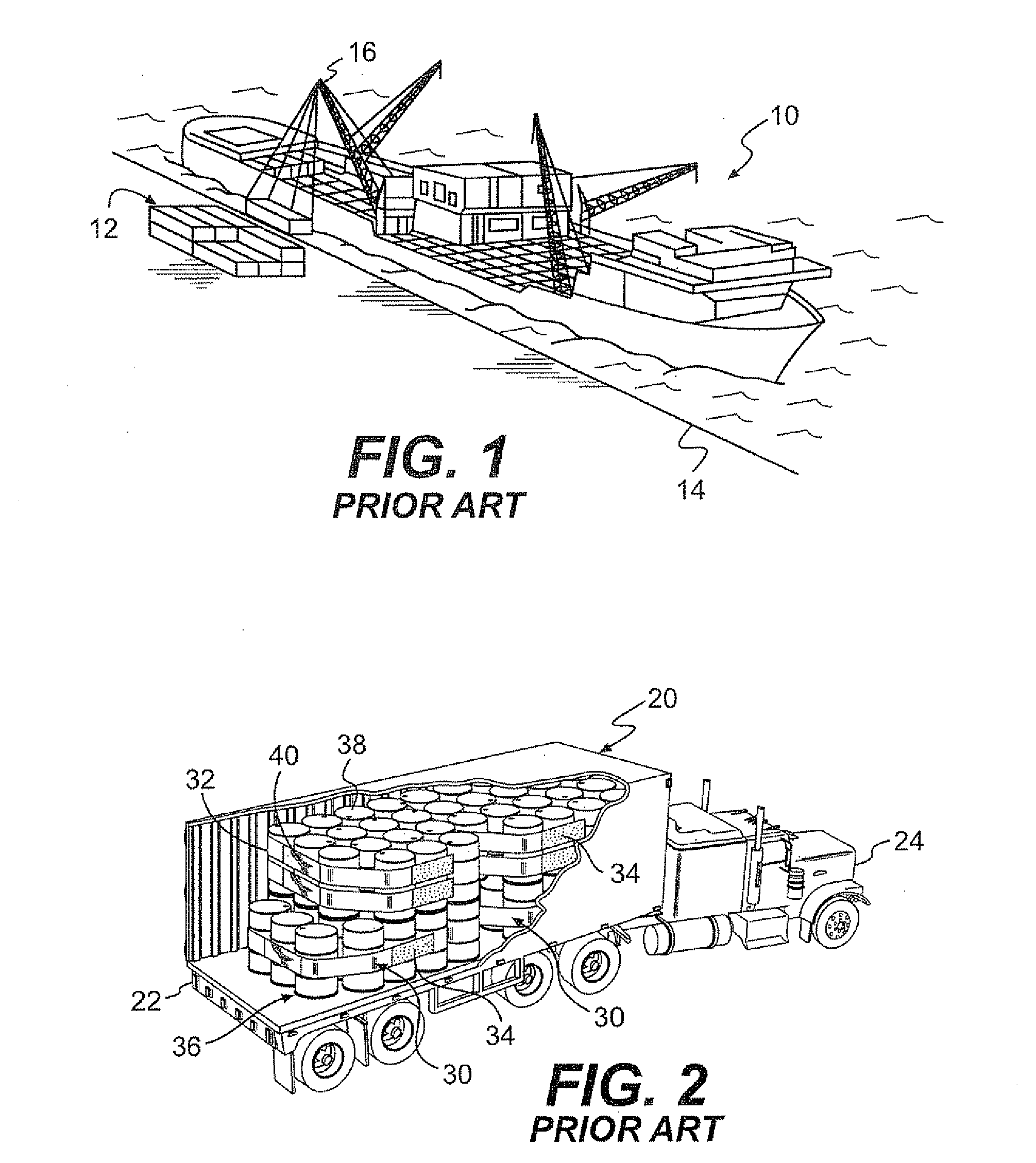
[0051]Referring now particularly to FIG. 1, there is shown one operative context of the subject invention. In this, a ship 10 is shown docked at a port and intermodal containers 12 are being loaded onto the ship. Specifically, FIG. 1 depicts the ship 10 at a dock 14 with cranes 16 lifting and loading the intermodal containers 12 to be stacked on the ocean going vessel 10. The subject invention may be advantageously used to secure cargo within intermodal containers, like the ones being loaded onto the ship 10, within rail cars, truck trailers and the like.

[0052]FIG. 2 is an axonometric view that discloses another operating environment of the invention. In this view an intermodal or cargo container 20 is shown mounted upon a trailer 22 which is operably towed by a tractor 24 for land transport. Containers such as these are also operable to be mounted on railway flat cars either directly or as attached to truck trailers 22.

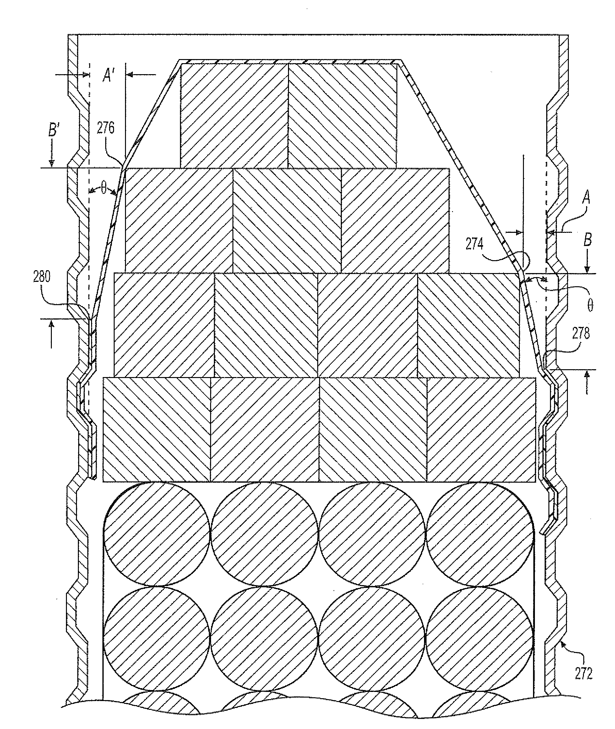
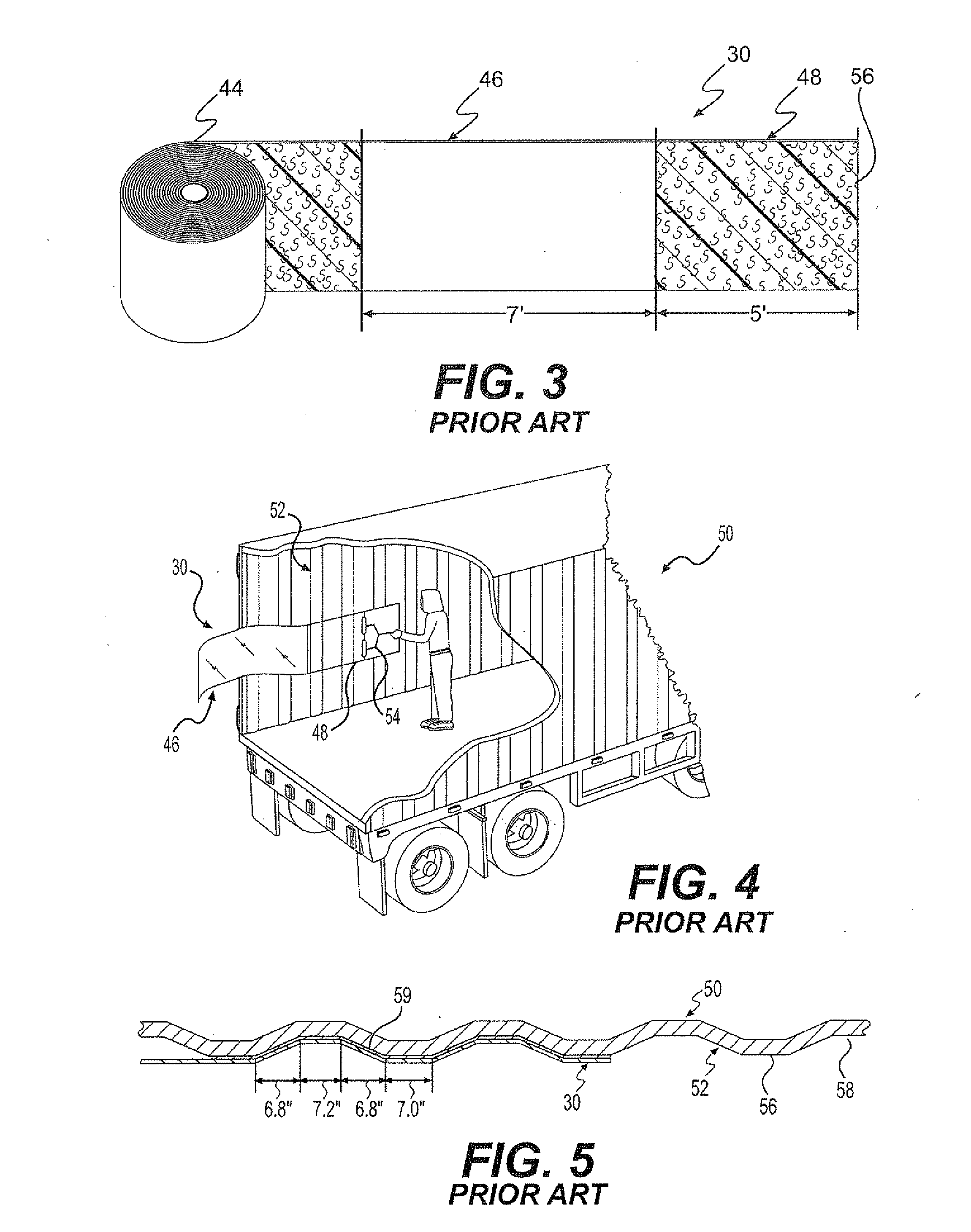
[0053]A partially cut away portion of F...


PUM

PropertyMeasurementUnit
Lengthaaaaaaaaaa
Lengthaaaaaaaaaa
Lengthaaaaaaaaaa

Abstract

A load restraint method and system for securing cargo within transport containers wherein the angle θ of attachment between a side wall of a container and a reinforcing strip of material attached to the side wall is maintained at 15 degrees or less in accordance with the formula B≦cot θ·A, where θ is the angle formed between an exterior surface of said load restraining strip and an interior plane of the lateral wall surface of the transport container “A” is the distance from a front edge of a load to an adjacent side wall and “B” is the distance along the wall of the container behind the point of contact of the restraining strip with an edge of the load to be restrained.

Description

RELATED PATENTS[0001]This application relates to U.S. Pat. No. 6,089,802 entitled “Cargo Restraint System for a Transport Container” issued on Jul. 18, 2000; U.S. Pat. No. 6,227,779 entitled “Cargo Restraint Method for a Transport Container” issued on May 8, 2001; U.S. Pat. No. 6.607,337 entitled “Cargo Restraint System” issued on Aug. 19, 2003; U.S. Pat. No. 6,896,459 issued on May 24, 2005; U.S. Pat. No. 6,923,609 issued on Aug. 2, 2005; U.S. Pat. No. 7,018,151 issued on Mar. 28, 2006; U.S. Pat. No. 7,066,698 issued on Jun. 27, 2006; U.S. Pat. No. 7,290,969 issued on Nov. 6, 2007; and U.S. Pat. No. 7,329,074 issued on Feb. 12, 2008 all of common inventorship and assignment as the subject application.BACKGROUND OF THE INVENTION [0002]This invention relates to an improved method and system for restraining cargo during transportation. More particularly, this invention relates to a novel method and system for securing and restraining undesired movement of drums, boxes, rigid and flexi...

Claims


Application Information

Patent Timeline
IPC IPC(8): B65D63/00B61D45/00
CPCB32B7/12B60P7/135B60P7/0823B32B27/08
Inventor BULLOCK, MATTHEW
Owner MBULL HLDG LLC
Why Eureka
Try Eureka