
Three-terminal design for spin accumulation magnetic sensor

a magnetic sensor and three-terminal technology, applied in the field of magnetoresistive sensors, can solve the problems of limited areal density and insufficient to achieve the signal-to-noise performance, and achieve the effect of reducing technical difficulties and signal-to-noise degradation, and increasing the density of areal recording

Active Publication Date: 2010-11-25
WESTERN DIGITAL TECH INC
View PDF18 Cites 26 Cited by
  • Summary
  • Abstract
  • Description
  • Claims
  • Application Information

AI Technical Summary

Benefits of technology

[0009]The present invention provides a spin accumulation read head sensor that has a three terminal design that allows the free layer to be located at the air bearing surface without unnecessary shunting of spin current, interference with the hard bias stabilization, or the fabrication difficulty of establishing a fourth contact at or near the air bearing surface. The sensor includes a reference layer structure located away from the air bearing surface and a free layer structure located at the air bearing surface. An internal non-magnetic, conductive spin-transport conducting layer extends from the reference layer structure to the free layer structure. For the present invention, removing the reference layer structure from the ABS allows its size to be substantially larger than that of the free layer structure, thereby reducing technical difficulties and signal-to-noise degradation associated with scaling down the size of the reference layer structure concomitantly with the free layer as required to achieve increased areal recording density.
[0010]A current or voltage source applied across the reference layer structure through a second lead connection results in spin-polarized electrical current through the reference layer which returns to a first current lead that is connected to a common “ground” connection. Simultaneously, a pure spin current can flow from the reference layer structure to and through the free layer structure through the aforementioned conductive spin-transport conducting layer. If the spin-conductance through the free layer is dependent on the orientation of the free layer magnetization relative to that of the reference layer, a (voltage sensing) amplifier connected to ground on one side, and to a third lead connection that is in electrical contact with the free-layer structure, can then detect a change in voltage generated across the free layer structure when the spin-current is modulated by the rotation of the free layer magnetization in response to magnetic signal fields from the rotating magnetic disk. For example, the conventional top and bottom magnetic shields of the read head can act as either of the first / ground and third lead connections (one shield being ground while the other is the third lead), such that the signal voltage is the measured electric potential difference between top and bottom shields, as is typically the case for a TMR sensor. However, because the third lead connection is the only external electrical connection to the free layer structure in the three-terminal design of the present invention, none of the spin current from the reference layer reaching the free layer structure will be otherwise shunted into a fourth lead connection to the opposite side of the free layer structure that is electrically connected to the third lead. In prior art spin accumulation devices a fourth lead is present and shunts some of the spin current, reducing the signal.
[0011]The free layer structure can include an insulating layer on that side (top or bottom) opposite to that electrically connected to the third lead, to keep it electrically insulated from direct contact to the shield layer serving as the first / ground lead connection. The free layer structure can also include a spin diffusion layer between the free layer and the shield acting as the third lead connection. This spin diffusion layer can be constructed of a metallic conductor having a short spin diffusion length, such as Pt, Ir or Re, and acts to diffuse the spin polarity of the spin current before it reaches the shield. This prevents the direction of the shield magnetization from playing the role of a second reference layer in influencing the spin-conductance through the free layer structure.

Problems solved by technology

Read sensor technology such as TMR was introduced when the technology preceding it was not able to deliver the necessary signal and signal-to-noise ratio al the necessarily smaller sensor sizes.
Similarly, TMR read sensors may find a limited range of device size (and hence limited areal density) below which it too may be inadequate to achieve necessary signal-to-noise performance.

Method used


Image

  • Three-terminal design for spin accumulation magnetic sensor
  • Three-terminal design for spin accumulation magnetic sensor
  • Three-terminal design for spin accumulation magnetic sensor

Examples


Embodiment Construction

[0019]The following description is of the best embodiments presently contemplated for carrying out this invention. This description is made for the purpose of illustrating the general principles of this invention and is not meant to limit the inventive concepts claimed herein.

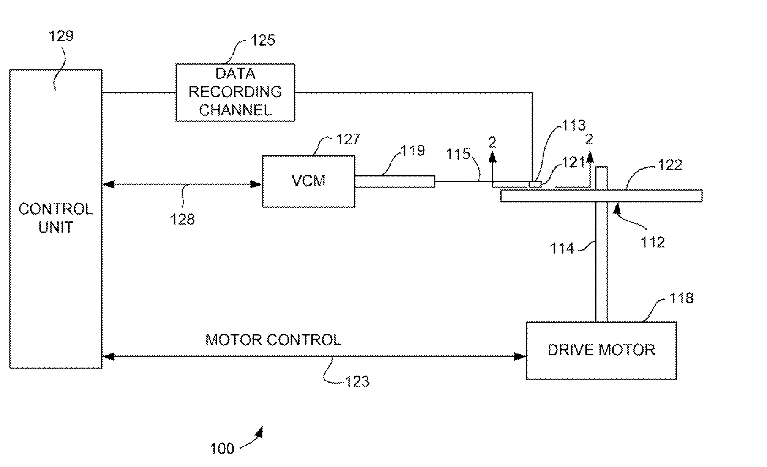
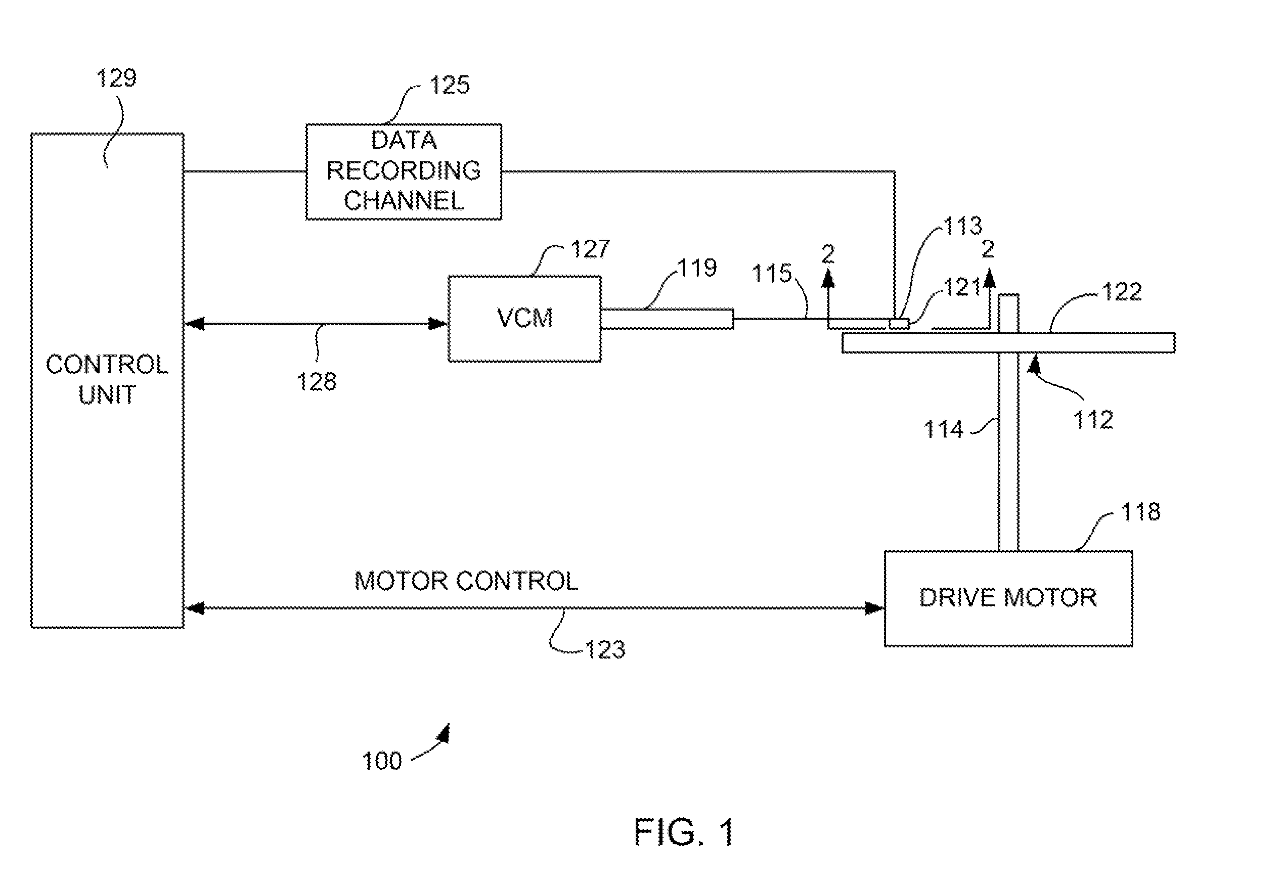
[0020]Referring now to FIG. 1, there is shown a disk drive 100 embodying this invention. As shown in FIG. 1, at least one rotatable magnetic disk 112 is supported on a spindle 114 and rotated by a disk drive motor 118. The magnetic recording on each disk is in the form of annular patterns of concentric data tracks (not shown) on the magnetic disk 112.

[0021]At least one slider 113 is positioned near the magnetic disk 112, each slider 113 supporting one or more magnetic head assemblies 121. As the magnetic disk rotates, slider 113 moves radially in and out over the disk surface 122 so that the magnetic head assembly 121 may access different tracks of the magnetic disk where desired data are written. Each slider 1...


PUM


Abstract

A spin accumulation sensor having a three terminal design that allows the free layer to be located at the air bearing surface. A non-magnetic conductive spin transport layer extends from a free layer structure (located at the ABS) to a reference layer structure removed from the ABS. The sensor includes a current or voltage source for applying a current across a reference layer structure. The current or voltage source has a lead that is connected with the non-magnetic spin transport layer and also to electric ground. Circuitry for measuring a signal voltage measures a voltage between a shield that is electrically connected with the free layer structure and the ground. The free layer structure can include a spin diffusion layer that ensures that all spin current is completely dissipated before reaching the lead to the voltage source, thereby preventing shunting of the spin current to the voltage source.

Description

FIELD OF THE INVENTION[0001]The present invention relates to magnetoresistive sensors and more particularly to a spin accumulation sensor having a three terminal configuration and a spin diffusion layer allowing the practical application of the spin accumulation sensor in a data recording system.BACKGROUND OF THE INVENTION[0002]The heart of a computer's long term memory is an assembly that is referred to as a magnetic disk drive. The magnetic disk drive includes a rotating magnetic disk, write and read heads that are suspended by a suspension arm adjacent to a surface of the rotating magnetic disk and an actuator that swings the suspension arm to place the read and write heads over selected circular tracks on the rotating disk. The read and write heads are directly located on a slider that has an air bearing surface (ABS). The suspension arm biases the slider toward the surface of the disk, and when the disk rotates, air adjacent to the disk moves along with the surface of the disk....

Claims


Application Information

Patent Timeline
IPC IPC(8): G11B5/33
CPCG01R33/098G01R33/1284G11B2005/0005G11B5/398G11B5/39
Inventor BOONE, JR., THOMAS DUDLEYGURNEY, BRUCE ALVINSMITH, NEIL
Owner WESTERN DIGITAL TECH INC
Learn More