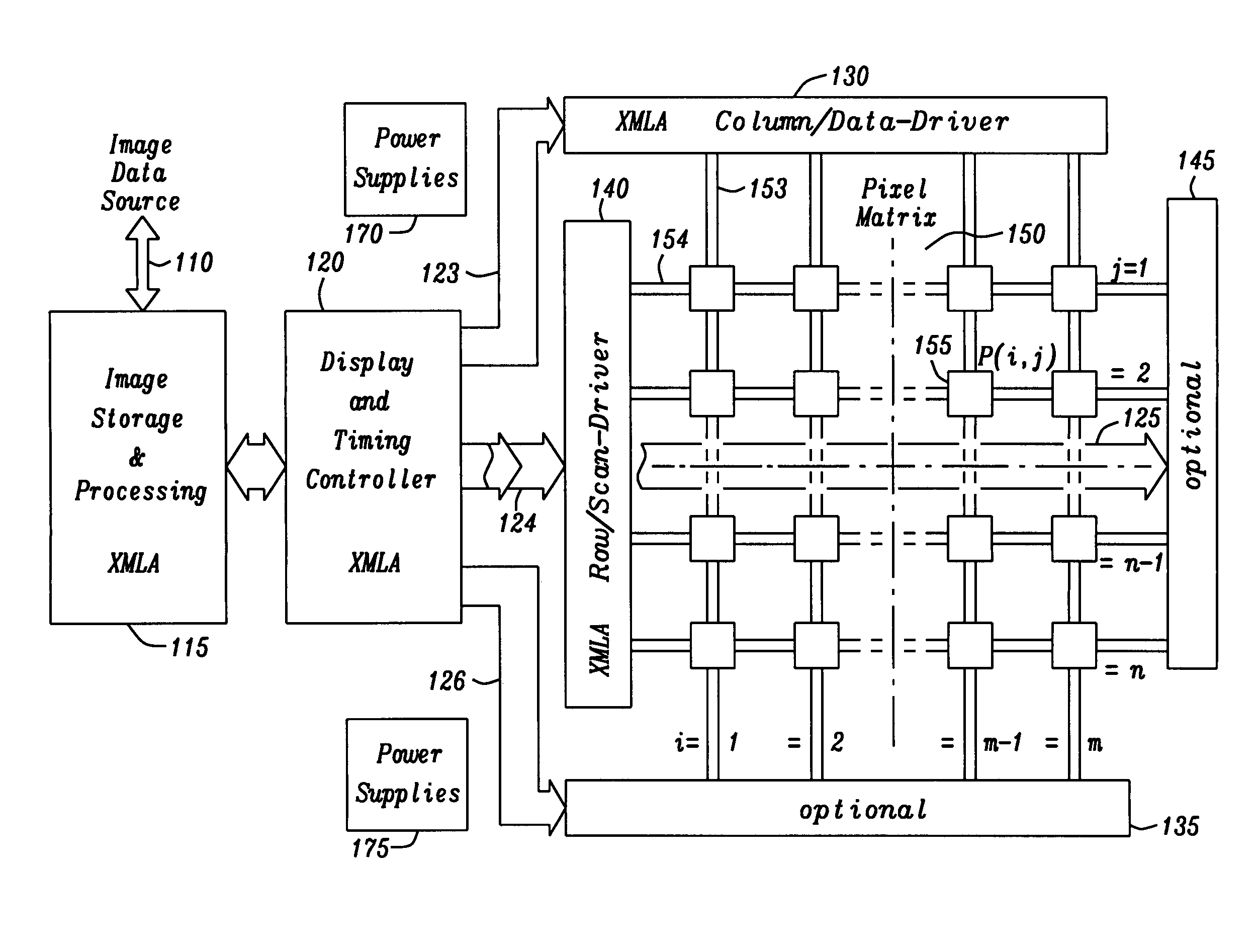
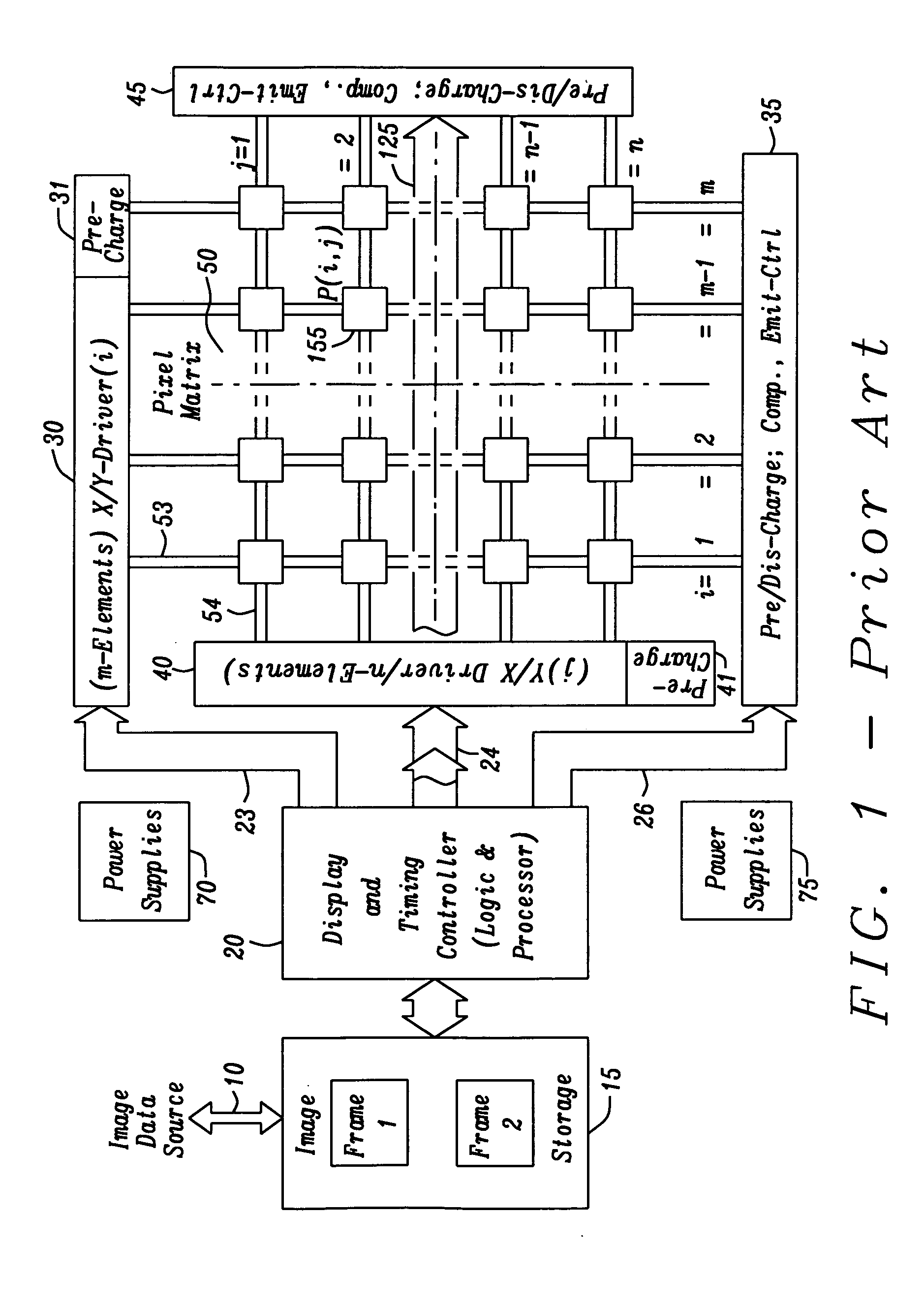
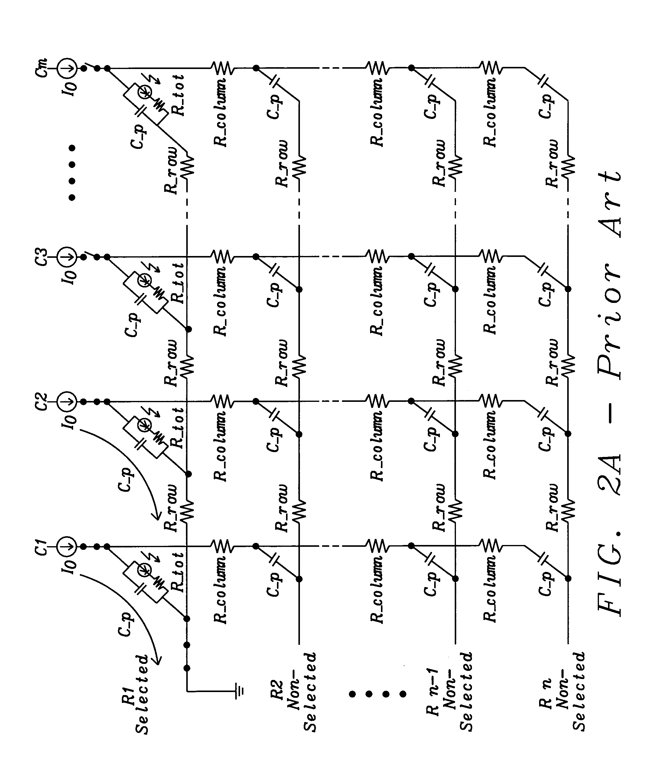
The larger the matrix becomes the longer the wires get with an increase of their harmful properties, such as resitivity losses on wires and parasitic capacitances between lines responsible e.g. for perturbing
crosstalk effects.
Although the PMOLED display has a simple configuration and an
advantage in terms of cost, the difficulty in realizing a display with
large size and high brightness as well as low
power consumption and high lifetime is limiting its use.
An
AMOLED display device has problems however in that variations in component characteristics of the pixel circuit may exist and thus brightness of each pixel which make up the display screen may vary.
However,
OLED technology in very large-screen or huge-screen display applications is currently still on its way into the
mass market; examples include huge time-table displays at
train stations, in airports, or at harbors, or displays for large marketing advertisements and
mass-public informational purposes including those displaying share prices in stock exchanges, and huge indoor or even outdoor stadium displays.
Therefore, the more light output needed, the more current has to be fed to the pixels which on the other hand is detrimental to the lifetime of the pixels.
However, the PMOLED displays used in many modern applications encounter several common issues when the displays become larger and especially if they should also display video streams with moving pictures.
These issues include sensible
higher power consumption, thus an elevated
operating temperature and, the larger they get a slower frame response with poorer contrast.
Having large numbers of vertical Column lines results in large currents to charge many
OLED pixels at once.
Preferably is, however, to allow individual pixels to remain on for a longer time and hence reduce the overall drive level.
In a PMOLED matrix configuration the brightness can vary across the area of a display and also with
operation time, temperature, and age, making it difficult to predict how bright a pixel will appear when driven by a
voltage.
Especially in color displays the accuracy of color representations may be affected.
Another major challenge with using PMOLED in
high resolution displays is that the operating lifetime is limited, as already adumbrated.
Modern MLA schemes have been further expanded and continuously developed into the Consecutive MLA (CMLA) scheme, a rather
complex matrix decomposition method combining MLA and
Single Line Addressing (SLA) techniques described in the WIPO
Patent Application (WO / 2007 / 079947 to Xu et al.) cited below, which however not in all cases delivers optimal solutions, sometimes even augmenting the number of necessary charging operations.
As can already be seen from the above the goal to both get the benefits of MLA schemes for FPD driving and at the same
time limit the
processing power requirements in favor of a low
power consumption and augmented life-time of the whole FPD product is not easy to attain, a multitude of MLA schemes have been proposed with varying success given the surplus expenses needed.
Problems encountered in actual pixel layouts include, for example, contact between pixel electrodes and
peripheral circuitry, stability of holding capacitances, and
transistor turn-off currents.
However, in actual reality, there arises the problem that a display unevenness of the display picture is caused due to the non-uniformity of the
threshold voltage and the charge drift mobility of the driver
transistor.
As a result, the luminance of each
diode will not have the same correspondence relation as the received pixel data, which in turn results in an uneven frame display.
However, the switching TFT has small current as it is turned on, and thus it needs longer compensation time, which will result in an irregular operation of the switching TFT and disability of the compensation mechanism.
However, with the
circuit design of a conventional
voltage compensation arrangement, it is essential that the nodes connected to both X and Y line nodes have a stable
voltage state during the “data writing” stage, otherwise, a
charge sharing issue will be generated at the frame display stage.
Accordingly, the conventional
voltage compensation arrangement is apt to exhibit the drawback that the the node X does not reach a stable voltage state for canceling the
threshold voltage of the driving TFT to be compensated due to inadequate time.
As a result, the
charge sharing issue is generated and the display luminance can not reach the predicted luminance in correspondence with the pixel voltage.
Such a leakage current is small in the ideal device, but will be significantly larger if a defect is present.
However these approaches use often solutions, which are somewhat technically complex and therefore also expensive in production.


