Vehicle periphery monitoring device, vehicle, vehicle periphery monitoring program, and vehicle periphery monitoring method

Active Publication Date: 2010-11-11
ARRIVER SOFTWARE AB
View PDF7 Cites 21 Cited by
  • Summary
  • Abstract
  • Description
  • Claims
  • Application Information

AI Technical Summary

Benefits of technology

[0008]In view of the above circumstances, an object to be solved by the present invention is to provide a vehicle periphery monitoring device, a vehicle, a vehicle periphery monitoring program, and a vehicle periphery monitoring method capable of identifying a type of an object with high accuracy, on the basis of a shape of an outline of an image portion of the object extracted from an acquired image by a camera.
[0013]In the vehicle periphery monitoring device and vehicle of the present invention, the size of the image portion of the object in the acquired image by the camera becomes smaller as the object becomes smaller, and also becomes smaller as the distance between the camera and the object becomes longer. Therefore, by performing the filtering process by the filtering unit on the basis of the distance between the camera and the object in real space corresponding to the first image portion detected by the distance detecting unit, and the assumed value of the width in the predetermined direction of the object, using the Gabor filter, in which the target edge width is set to be narrower as the assumed value of the width is smaller and the distance is longer, and the target edge direction is set to a direction orthogonal to the predetermined direction, it becomes possible to extract the second image portion, while emphasizing only the edge region in a direction orthogonal to the predetermined direction of the target edge width that is assumed to be the image portion of the object of the specific type. Thereafter, it becomes possible to identify the type of the object in real space corresponding to the second image portion with high accuracy, on the basis of the shape of the second image portion extracted as explained above.
[0015]According to the present invention, it becomes possible to extract the second image portion effectively, by reducing the calculation amount during the filtering process, which is made possible by carrying out the filtering process only to the local processing region surrounding the first image portion set by the local processing region setting unit.
[0017]According to the present invention, in the case where the second image portion having the edge width in the horizontal direction corresponding to the distance of the assumed value of the width in the horizontal direction of the pedestrian, and having the edge direction in the vertical direction, is extracted by the filtering process from the acquired image by the camera, it is evaluated that the second image portion includes an image portion of a leg of a pedestrian, when the lower end of the second image portion is included in the lower half region of the local processing region. Therefore, it becomes possible to identify that the type of the object in real space corresponding to the second image portion is a pedestrian.
[0023]In the present invention, the size of the image portion of the object in the acquired image of the camera becomes smaller as the object becomes smaller, and also becomes smaller as the distance between the camera and the object becomes longer. Therefore, by performing the filtering process in the filtering step on the basis of the distance between the camera and the object in real space corresponding to the first image portion detected in the distance detecting step, and the assumed value of the width in the predetermined direction of the object, using the Gabor filter, in which the target edge width is set to be narrower as the assumed value of the width is smaller and the distance is longer, and the target edge direction is set to be a direction orthogonal to the predetermined direction, it becomes possible to extract the second image portion, while emphasizing only the edge region in a direction orthogonal to the predetermined direction of the target edge width that is assumed to be the image portion of the object of the specific type. Thereafter, it becomes possible to identify the type of the object in real space corresponding to the second image portion with high accuracy, on the basis of the shape of the second image portion extracted as explained above, in the object type identifying step.

Problems solved by technology

However, in the case of determining whether or not the object is a human being on the basis of the width between edges, there is an inconvenience that the width of the image portion of the object is not properly calculated, when image portions of a plurality of objects are included in the window.
As such, there is an inconvenience that the identification accuracy of the type of the object is reduced.

Method used


Image

  • Vehicle periphery monitoring device, vehicle, vehicle periphery monitoring program, and vehicle periphery monitoring method
  • Vehicle periphery monitoring device, vehicle, vehicle periphery monitoring program, and vehicle periphery monitoring method
  • Vehicle periphery monitoring device, vehicle, vehicle periphery monitoring program, and vehicle periphery monitoring method

Examples


Embodiment Construction

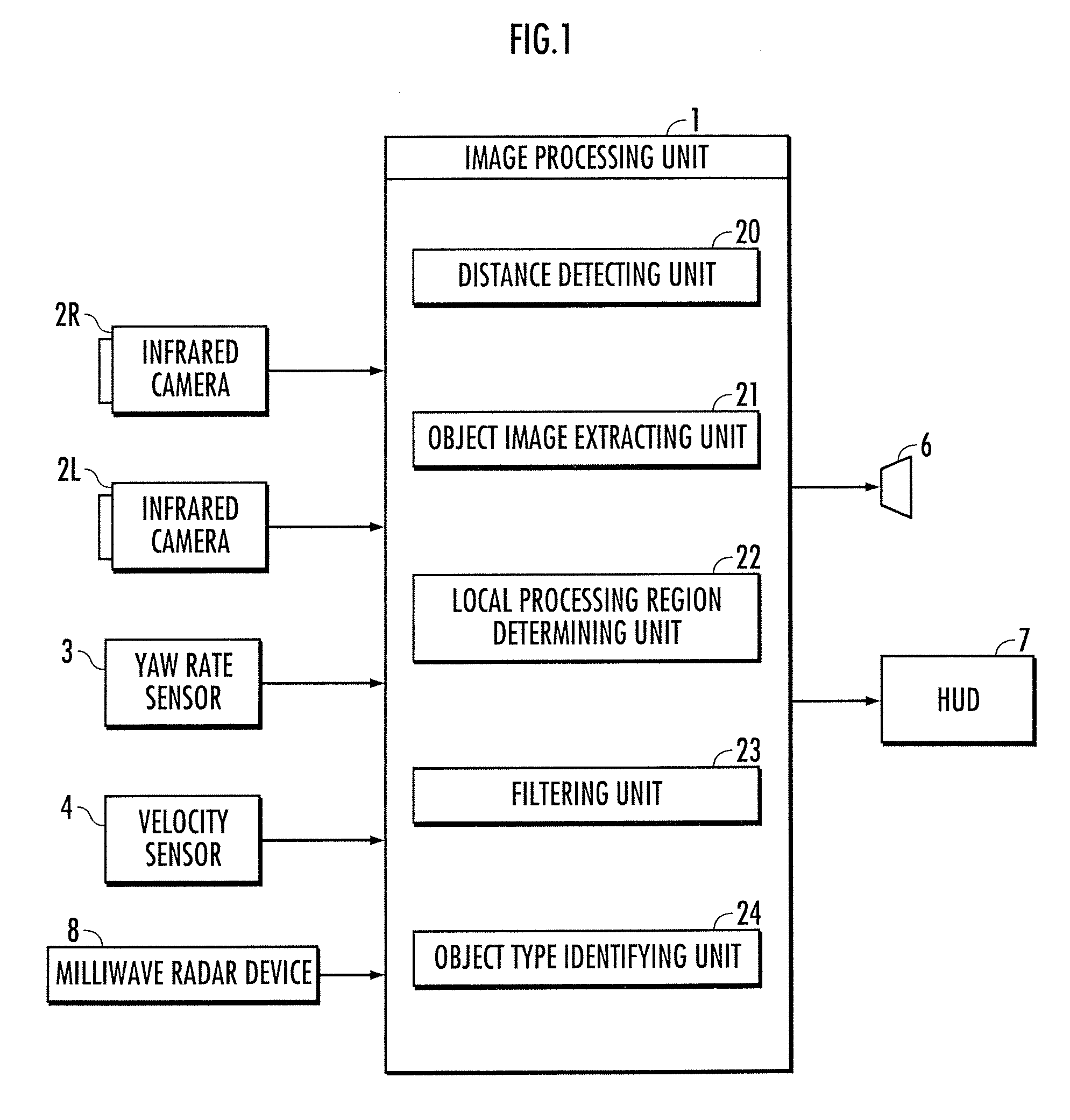
[0032]An embodiment of the present invention will now be explained below with reference to FIG. 1 through FIG. 8. FIG. 1 is a configuration diagram of a vehicle periphery monitoring device of the present invention. The vehicle periphery monitoring device of the present invention is equipped with an image processing unit 1, infrared cameras (corresponds to the camera of the present invention) 2R, 2L capable of detecting far-infrared rays, a yaw rate sensor 3 for detecting yaw rate of the vehicle, a velocity sensor 4 for detecting the traveling speed of the vehicle, a loudspeaker 6 for performing warning by sound, a head-up display (hereinafter referred to as HUD) 7 for performing display to make the driver observe an object, and a milliwave radar device 8 for detecting distance between the cameras 2R, 2L and the object.

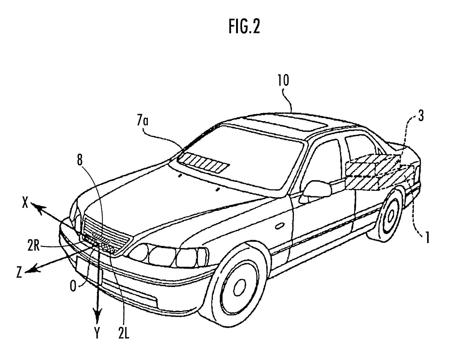
[0033]With reference to FIG. 2, the infrared cameras 2R, 2L are arranged at the front of a vehicle 10, at the positions approximately symmetrical with respect to the c...


PUM


Abstract

A vehicle periphery monitoring device comprising a distance detecting unit which detects the distance between cameras and an object, an object image extracting unit which extracts a first image portion of the object from the acquired image, a filtering unit which performs a filtering process to the acquired image, in which a target edge width is set to be narrower as the assumed value of the width is smaller and the distance is longer, and in which a target edge direction is set to a direction orthogonal to the predetermined direction, and an object type identifying unit which identifies, on the basis of a shape of a second image portion extracted by the filtering process, whether or not the type of the object in real space corresponding to the second image portion is the specific type.

Description

BACKGROUND OF THE INVENTION[0001]1. Technical Field[0002]The present invention relates to a vehicle periphery monitoring device, vehicle, vehicle periphery monitoring program, and vehicle periphery monitoring method which monitors a periphery of a vehicle by detecting an object present in the periphery of the vehicle, from an acquired image of the periphery of the vehicle by a camera mounted on the vehicle.[0003]2. Description of the Related Art[0004]There is known a vehicle periphery monitoring device which detects an object in a periphery of a vehicle from an acquired image of the periphery of the vehicle by a camera mounted on the vehicle, calculates a relative position and relative velocity of the object in real space and the vehicle, and determines a possibility of contact between the vehicle and the object within a predetermined time (for example, refer to Japanese Patent Laid-Open No. 2001-6096).[0005]Further, in order to identify a type of the object (human being, vehicle, l...

Claims


Application Information

Patent Timeline
IPC IPC(8): H04N7/18G06T7/00G06K9/00
CPCG06K9/00805B60R1/00G06V20/58
Inventor YOKOCHI, YUJINAGAOKA, NOBUHARUTANIGUCHI, FUMINORI
Owner ARRIVER SOFTWARE AB
Why Eureka
Try Eureka