
Linear transimpedance amplifier with wide dynamic range for high rate applications

a transimpedance amplifier and dynamic range technology, applied in the field of transimpedance amplifiers, can solve the problems of increasing non-linearity and distortion of prior art amplifiers, and the inability to correct the distortion introduced by the amplifier 108, and achieve the effect of improving performance characteristics

Active Publication Date: 2010-11-11
MACOM TECH SOLUTIONS HLDG INC
View PDF14 Cites 22 Cited by
  • Summary
  • Abstract
  • Description
  • Claims
  • Application Information

AI Technical Summary

Benefits of technology

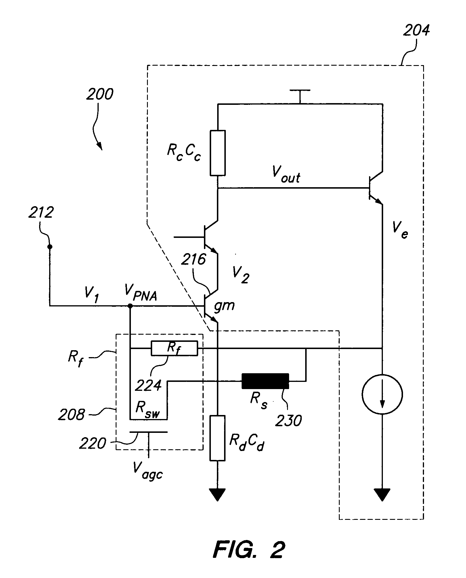
[0012]Also disclosed herein is a transimpedance amplifier comprising an input configured to receive an input signal and an amplifier configured to amplify the input signal to create an amplified signal. The amplifier also has an output configured to output the amplified signal. A feedback loop having a feedback resistance is part of the system and it has a feedback resistance comprising a switch resistance, a feedback resistor in parallel with the switch resistance, and a divider element. The divider element is in parallel with the feedback resistance and is in series with the switch resistance to create a combined switch resistance. The divider element reduces the effect of changes in the switch resistance on the combined resistance.

Problems solved by technology

The equalizer is primarily configured to combat dispersion and as a result, distortion introduced by the amplifier 108 can not be corrected by the equalizer.
While prior art amplifiers performed acceptably at lower rates, such as rates in 1 to 2 gigabit per second transmit range, as transmit rates increase, prior art amplifiers suffered from increased non-linearity and distortion.

Method used


Image

  • Linear transimpedance amplifier with wide dynamic range for high rate applications
  • Linear transimpedance amplifier with wide dynamic range for high rate applications
  • Linear transimpedance amplifier with wide dynamic range for high rate applications

Examples


Embodiment Construction

[0030]The example environment of FIG. 1 is but one possible environment of use and is provided to aid in understanding. It is contemplated that the innovations disclosed herein may be utilized in any environment which would benefit from an accurate and linear TIA amplifier. After reading the following disclosure, one of ordinary skill in the art may determine numerous different environments of use for the disclosed innovations.

[0031]FIG. 2 illustrates a circuit level block diagram of one innovation to address the drawback in the prior art. This circuit illustrates an exemplary TIA device 200. In general, amplifier element 204 may be broadly described as the amplifier while gain control loop 208 serves as a voltage based automatic gain control. Also part of the embodiment of FIG. 2 is a collector resistor capacitance RcCc and a degeneration resistance capacitance RdCd. These elements are described below in more detail.

[0032]In this circuit, an input 212 connects to a transistor 216, ...


PUM


Abstract

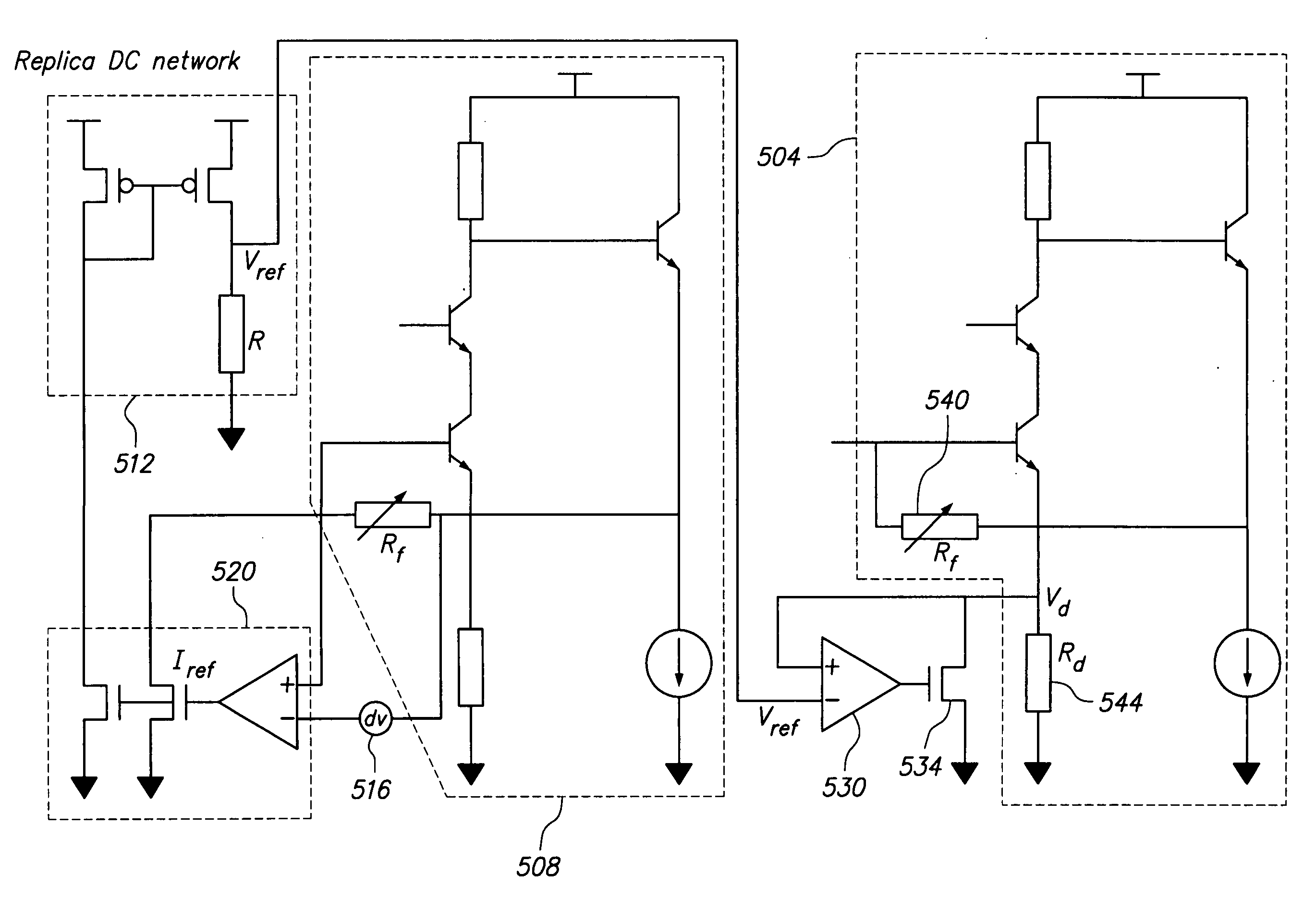
Various amplifier configurations having increased bandwidth, linearity, dynamic range, and less distortion are shown and disclosed. To increase bandwidth in a transimpedance amplifier, a replica circuit is created to replicate a degeneration resistance, or the resistance or value that relates to a feedback resistance. From the replica circuit, the replicated values are mirrored and processed to control a FET switch which modifies a degeneration resistance. The FET switch control signal is related to the feedback resistance and modifies the degeneration resistance to thereby maintain the product of the feedback resistance and the degeneration resistance as a constant. In another embodiment, a second switch controlled by an automatic gain control signal is established between a first stage amplifier and a second stage amplifier to improve dynamic range and bandwidth without degrading other amplifier specifications.

Description

FIELD OF THE INVENTION[0001]The invention relates to transimpedance amplifiers and in particular to a method and apparatus for increasing dynamic range, linearity, and stability of a transimpedance amplifier.Related Art[0002]FIG. 1 illustrates an example environment of use. In this example environment, an optical fiber 100 provides an optical signal to a photodetector 104. The photodetector 104 converts the optical signal to a low power electrical current. To facilitate downstream processing the resulting electrical signal must be amplified. The output from the photodetector 104 feeds into an amplifier 108, which increases the power level of the input to a level suitable for downstream processing and decoding. One type of amplifier often utilized for this application is a transimpedance amplifier (TIA), which is a low noise current to voltage amplifier.[0003]The output of the amplifier 108 feeds into an equalizer 112. In this configuration the equalizer 112 comprises an electronic d...

Claims


Application Information

Patent Timeline
Patent Type & Authority Applications(United States)
IPC IPC(8): H03G3/30H03F3/45H03F3/16
CPCH03F1/083H03F1/22H03F1/34H03F3/087H03F3/45098H03G1/007H03F2200/156H03F2200/453H03F2203/45652H03G1/0017H03G1/0029H03F3/45475
Inventor SHIVARAM, KRISHNAAHMED, KASHIF A.
Owner MACOM TECH SOLUTIONS HLDG INC
Learn More