
Chip package structure and manufacturing method thereof

a technology of chip package and manufacturing method, which is applied in the direction of semiconductor devices, semiconductor/solid-state device details, electrical apparatus, etc., can solve the problems of reducing the the oxidization of copper, and the reduction of the reliability and strength of the bonding wire, so as to achieve the effect of reducing manufacturing costs and improving yield and reliability of the chip package structur

Inactive Publication Date: 2010-10-21
UNIMICRON TECH CORP
View PDF6 Cites 4 Cited by
  • Summary
  • Abstract
  • Description
  • Claims
  • Application Information

AI Technical Summary

Benefits of technology

[0007]The present application is directed to a chip package structure and a manufacturing method thereof for effectively lowering manufacturing costs and improving yield and reliability of the chip package structure.
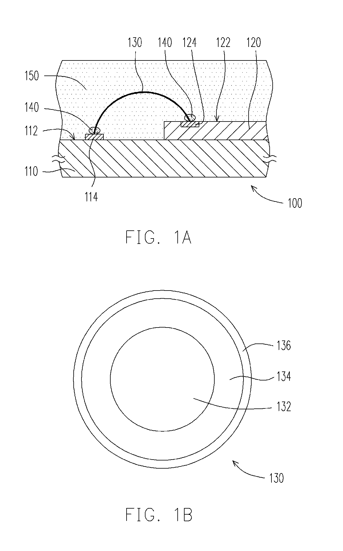
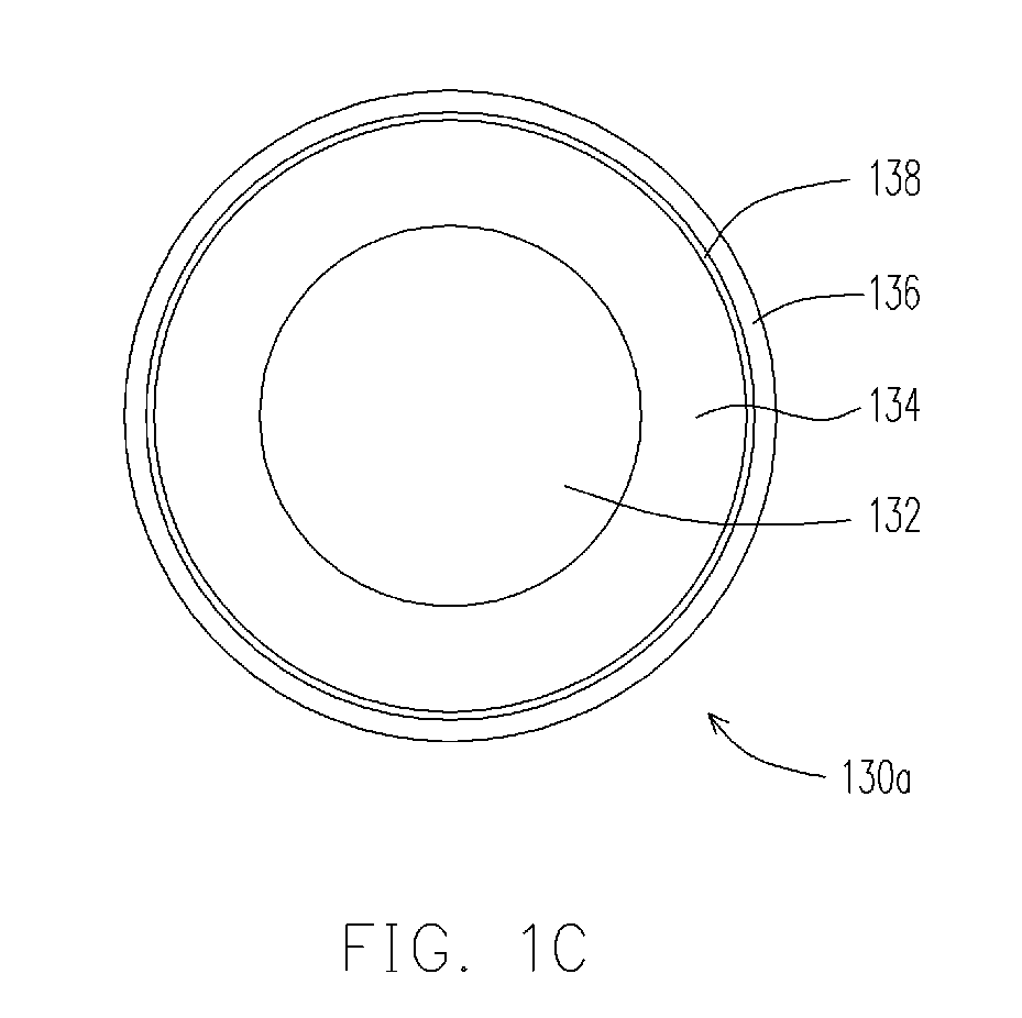
[0025]Based on the above, the bonding wire of the chip package structure in the present application is composed of a copper layer, a nickel layer, and a gold layer. Besides, an adhesive layer is formed between the bonding wire and the pad of the circuit substrate and between the bonding wire and the contact pad of the chip. In addition, the bonding strength among the bonding wire, the pad, the contact pad, and the adhesive layer is enhanced by performing an ultrasonic bonding process. Accordingly, compared with the conventional bonding wire, the bonding wire of the present application not only can effectively reduce the manufacturing costs of the chip package structure but also can feasibly improve strength, reliability, and yield of the chip package structure.

Problems solved by technology

However, copper is prone to be oxidized, and utilization of copper as the material of the bonding wire likely gives rise to oxidation, such that reliability and strength of the bonding wire both decrease.
On the other hand, given that gold having a lower thermal conductivity than that of copper is employed as the material of the bonding wire, the bonding wire is not subject to oxidation, whereas manufacturing costs of the bonding wire are raised due to high costs of gold in comparison with costs of copper and aluminum.

Method used


Image

  • Chip package structure and manufacturing method thereof
  • Chip package structure and manufacturing method thereof
  • Chip package structure and manufacturing method thereof

Examples


Embodiment Construction

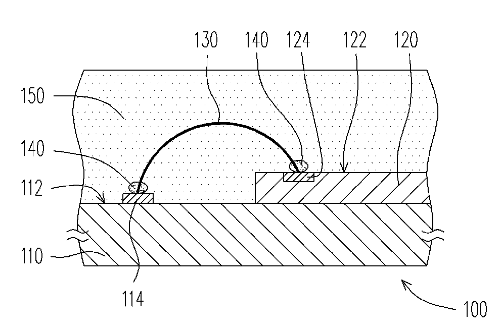
[0032]FIG. 1A is a schematic view of a chip package structure according to an exemplary embodiment of the present invention. FIG. 1B is a schematic top view of a bonding wire depicted in FIG. 1A. As shown in FIGS. 1A and 1B, in the present embodiment, the chip package structure 100 includes a circuit substrate 110, a chip 120, at least one bonding wire 130 (only one is schematically depicted in FIG. 1A), and an adhesive layer 140.

[0033]In detail, the circuit substrate 110 has a bonding surface 112 and at least one pad 114 (only one is schematically depicted in FIG. 1A) disposed on the bonding surface 112. According to the present embodiment, the circuit substrate 110 is, for instance, a printed circuit board (PCB). A material of the pad 114 is gold or copper, for example. In general, given that the material of the pad 114 is copper, a surface of the pad 114 is frequently covered by a nickel layer and a gold layer to prevent oxidation and other environmental conditions from affecting...


PUM


Abstract

A chip package structure includes a circuit substrate, a chip, at least one bonding wire, and an adhesive layer. The circuit substrate has a bonding surface and at least one pad disposed on the bonding surface. The chip is disposed on the bonding surface of the circuit substrate and has an active surface away from the circuit substrate and at least one contact pad disposed on the active surface. The bonding wire is connected between the contact pad and the pad, such that the chip is electrically connected to the circuit substrate through the bonding wire. The bonding wire includes a copper layer, a nickel layer covering the copper layer, and a gold layer covering the nickel layer. The adhesive layer is disposed between the pad and the bonding wire and between the contact pad and the bonding wire and respectively covers two terminals of the bonding wire.

Description

CROSS-REFERENCE TO RELATED APPLICATION[0001]This application claims the priority benefit of Taiwan application serial no. 98112809, filed Apr. 17, 2009. The entirety of the above-mentioned patent application is hereby incorporated by reference herein and made a part of specification.BACKGROUND OF THE INVENTION[0002]1. Field of the Invention[0003]The present application relates to a semiconductor structure and a manufacturing method thereof. More particularly, the present application relates to a chip package structure and a manufacturing method thereof.[0004]2. Description of Related Art[0005]A wire bonding technology applied for electrically connecting a chip to a carrier is a common chip package technology. Here, the carrier is a circuit substrate, for example. In general, the wire bonding technology is applied by forming a wire bump on a pad of the carrier with use of a stud bump machine, extending a wire upward to a certain distance, pulling the wire down to a contact pad of the...

Claims


Application Information

Patent Timeline
IPC IPC(8): H01L23/49H01L21/607
CPCH01L24/45H01L2924/00015H01L24/85H01L2224/45572H01L2224/45573H01L2224/45644H01L2224/45647H01L2224/45655H01L2224/45664H01L2224/48091H01L2224/48227H01L2224/48464H01L2224/48475H01L2224/48599H01L2224/48699H01L2224/48992H01L2224/48997H01L2224/85051H01L2224/85205H01L2224/8592H01L2924/01013H01L2924/01028H01L2924/01029H01L2924/01046H01L2924/0105H01L2924/01074H01L2924/01079H01L2924/01322H01L24/48H01L2924/01033H01L2924/01019H01L2224/45147H01L2924/00014H01L2224/78H01L2924/00H01L2224/45144H01L2224/45124H01L2224/05644H01L2224/85444H01L2224/85447H01L2224/85455H01L2224/8585H01L2924/181H01L2924/00012
Inventor WU, CHUNG-PAN
Owner UNIMICRON TECH CORP
Learn More