
Method of controlling single crystal diameter

a single crystal and diameter technology, applied in the direction of single crystal growth, polycrystalline material growth, eutectic material solidification, etc., can solve the problems of product quality, incur enormous loss, and shorten the total length of the single crystal

Active Publication Date: 2010-10-21
SUMCO CORP
View PDF5 Cites 8 Cited by
  • Summary
  • Abstract
  • Description
  • Claims
  • Application Information

AI Technical Summary

Benefits of technology

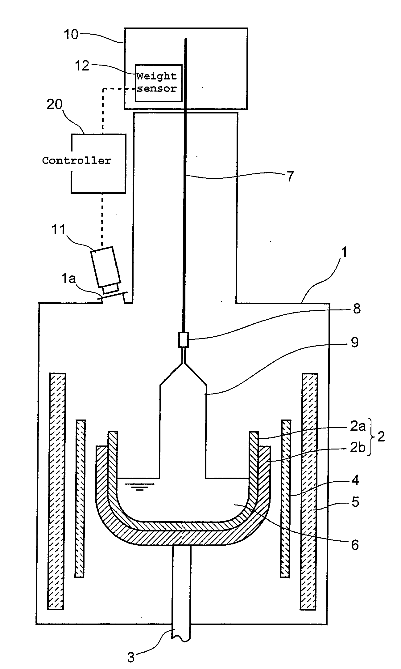
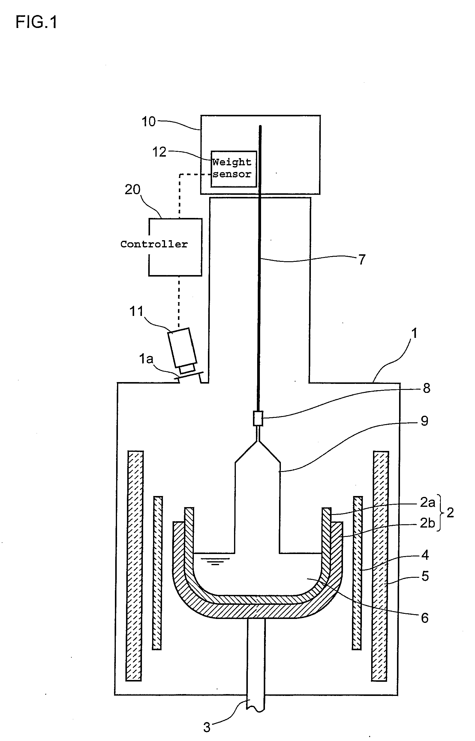
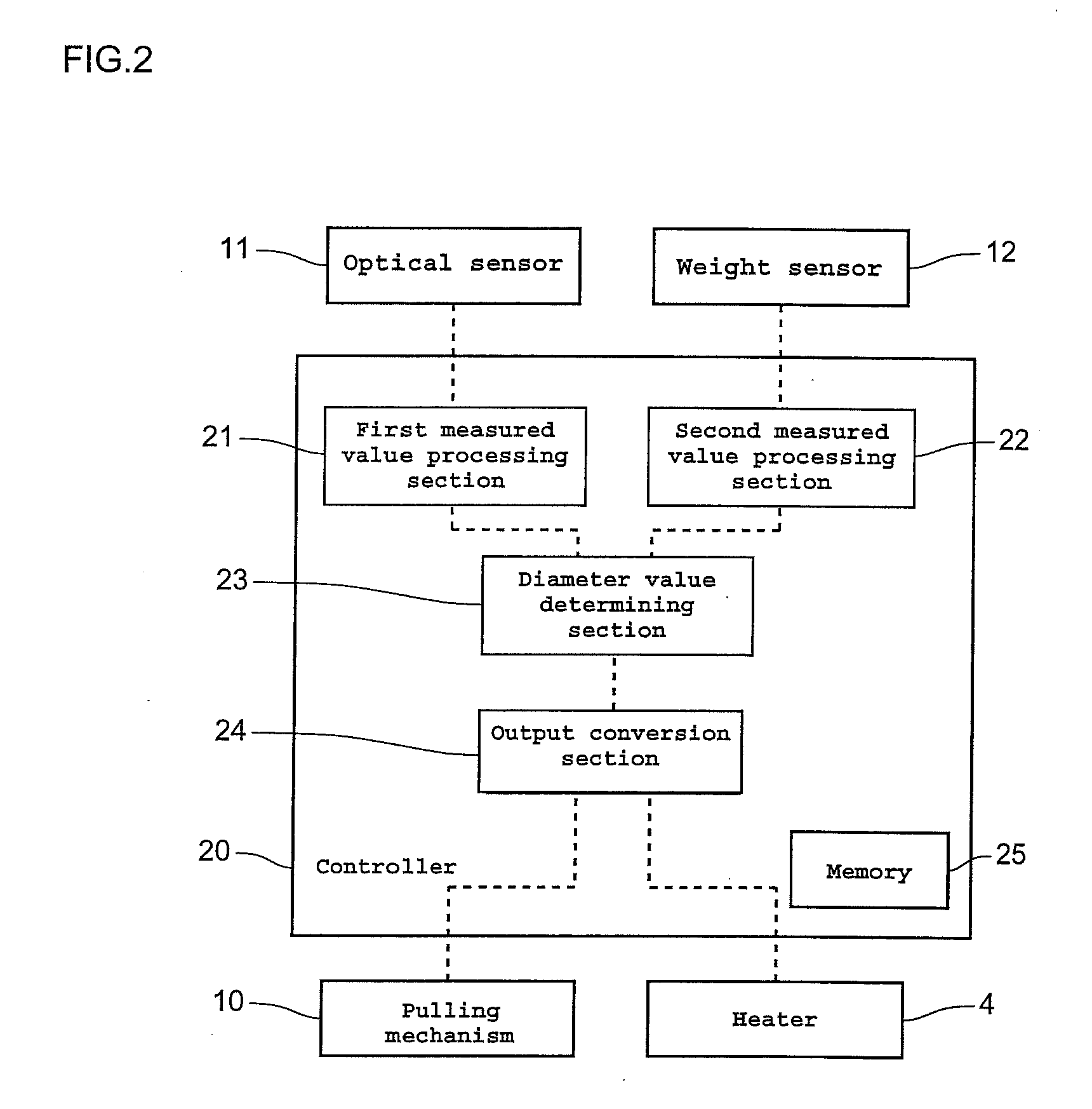
The present invention provides a method of controlling the diameter of a single crystal during growth using both optical and weight systems simultaneously. This allows for accurate measurement of the diameter of the single crystal and ensures appropriate control of the diameter as compared to the diameter value evaluated only by the optical system or the weight system. The method includes sequential accumulation of first and second measured values and updating the coefficient of a formula used for calculation of the diameter value on the basis of average values of the accumulated first and second measured values within a predetermined period.

Problems solved by technology

If a measured diameter of a single crystal is misjudged to be larger than the actual diameter, the product quality is adversely influenced because the actual single crystal diameter is small, and further defective products are generated because the diameter of the single crystal does not reach the diameter of the product, which might incur an enormous loss.
On the other hand, if the measured diameter of a single crystal is misjudged to be smaller than the actual diameter, the total length of the single crystal is shortened because the actual diameter of the single crystal is large, which might decrease the yield of the product.
However, the distance from the optical sensor to the fusion ring to be measured may fluctuate due to the effects such as the strain of the wire (pulling shaft) in association with progression of the single crystal growth, and issues related to materials (quartz crucible, graphite crucible, and polysilicon) like dimensional accuracy, degradation and weight change.
Therefore, in the diameter measurement by the optical system, it is difficult to detect the error of the diameter fluctuation occurring in the direction of the crystal growth, resulting in the lack of reliability in accuracy of the measured diameter of the single crystal.
However, since it requires a processing for excluding the influence on the diameter fluctuation which is attributable to the buoyancy acting on the growing single crystal, its responsiveness is poor.
Hence, it is difficult to detect the spread of the microscopic diameter fluctuation, resulting in the lack of reliability in accuracy of the measured diameter of the single crystal.
However, also in the method of controlling the diameter of a single crystal disclosed in Japanese Patent Application Publication No. 2003-176199, the fact remains that the diameter measurement is carried out by either the optical system or the weight system at individual growth stages respectively, and therefore the diameter of a growing single crystal cannot be accurately measured.

Method used


Image

  • Method of controlling single crystal diameter
  • Method of controlling single crystal diameter
  • Method of controlling single crystal diameter

Examples


example 1

[0054]A test was performed in which a single crystal ingot capable of assuring a diameter of 12 inches after processing its outer periphery was grown. In the test, the diameter measurement by the optical system using a one-dimensional camera and the diameter measurement by the weight system using a load cell were carried out, and the behavior of the diameter value by the measurement by the optical system and the behavior of the diameter difference (correction amount) when the measured value of the diameter by the optical system is corrected with the measured value of the diameter by the weight system were examined along a crystal length-wise direction. In the test of Inventive Example 1, the average value of the measured values of the diameter in formula (2) above was evaluated by the moving average, and 60, 45, 30 and 15 min are adopted as a period of time for the moving average.

[0055]FIGS. 3A to 3D depict the test results of Inventive Example 1. The average values of the measureme...

example 2

[0056]In Example 2, a test of growing a single crystal ingot as well as an examination was carried out as similarly as in Example 1 above. In the test of Inventive Example 2, the average value of the measured values of the diameter was evaluated by the least squares method, and 60 and 15 min are adopted as a period of time for evaluating the average value.

[0057]FIGS. 4A and 4B depict the test results of Example 2. The average values of the measurement values of the diameter for 60 and 15 min of time period are shown in FIGS. 4A and 4B, respectively. As shown in FIGS. 4A and 4B, in both cases of 15 and 60 min calculation time period, the scatter of correction amount is small, and therefore stable correction is possible.

[0058]According to the method of controlling a single crystal diameter of the present invention, since a diameter value of a single crystal is calculated on the basis of a first measured values of the single crystal diameter derived from the diameter measurement by the...


PUM

PropertyMeasurementUnit
diameteraaaaaaaaaa
diameteraaaaaaaaaa
weightaaaaaaaaaa

Abstract

When pulling and growing a single crystal from a raw material melt by the Czochralski method, a boundary between the single crystal and the raw material melt is imaged by an optical sensor, and also the weight of the single crystal is measured by a weight sensor, a diameter value of the single crystal is calculated on the basis of first measured values of the diameter of the single crystal derived from image data captured by the optical sensor and second measured values of the diameter of the single crystal derived from weight data captured by the weight sensor, and a pulling rate of the single crystal and the temperature of the raw material melt are adjusted on the basis of the calculated diameter value to thereby control the diameter of the single crystal, and thus it is possible to accurately measure the diameter of a growing single crystal.

Description

BACKGROUND OF THE INVENTION[0001]1. Field of the Invention[0002]The present invention relates to a method of controlling the diameter of a single crystal when the single crystal is pulled and grown from a raw material melt by the Czochralski method (hereinafter, referred to as the “CZ method”), and particularly to a method of controlling the diameter of a single crystal that enables the precise measurement of diameter of a growing single crystal.[0003]2. Description of the Related Art[0004]A single crystal silicon is a material for a silicon wafer used for a semiconductor device, and the CZ method excellent in mass production is widely adopted for the production of the single crystal silicon. During the growing of a single crystal by the CZ method, a seed crystal is dipped into a raw material melt of silicon retained in a crucible within a chamber maintained in an inert atmosphere under reduced pressure, and the dipped seed crystal is gradually pulled, thereby growing a single cryst...

Claims


Application Information

Patent Timeline
Patent Type & Authority Applications(United States)
IPC IPC(8): C30B15/28
CPCC30B15/28C30B15/26Y10T117/1004Y10T117/1012
Inventor HAMADA, KEN
Owner SUMCO CORP
Learn More