
Method of fast-multicast and a system thereof

a fast-multicast and multicast technology, applied in the field of multicast system, can solve the problems of multicast application delay generation and multicast delay definitely

Inactive Publication Date: 2010-10-14
ZTE CORP
View PDF12 Cites 26 Cited by
  • Summary
  • Abstract
  • Description
  • Claims
  • Application Information

AI Technical Summary

Benefits of technology

[0024](a4) after the management module receives the time domain monitoring result of the multicast service, it determines the edge node of each multicast service in the next cycle and saves it.
[0030]Additionally, the above method also possesses the following characteristic: when said management module closes, it saves current mapping table; when the management module, Manager, restarts and builds up the connection with agent module, based on the saved edge node information in the mapping table, it notifies the agent module of these edge nodes to initiate the static multicast member of the corresponding multicast service in the table.
[0047]Compared with the existing multicast, and in the application environment that has relatively rich bandwidth and has a higher demand for high speed, the present invention can offer faster multicast service for the receiving end through the determination of the edge node and the initiation of the static multicast member on this node. This invention also possesses characteristics such as easy realization and good compatibility with current multicast protocols.

Problems solved by technology

The technical problem is targeted for the real-time application demands from some multicast services.
The multicast application delay is generated due to the randomness of multicast application requirements in the time domain.
In the traditional dynamic multicast method, small portion of these discrete points will lead to demolition and reconstruction of a huge multicast tree, resulting in a multicast delay definitely.

Method used


Image

  • Method of fast-multicast and a system thereof
  • Method of fast-multicast and a system thereof

Examples


first embodiment

The First Embodiment

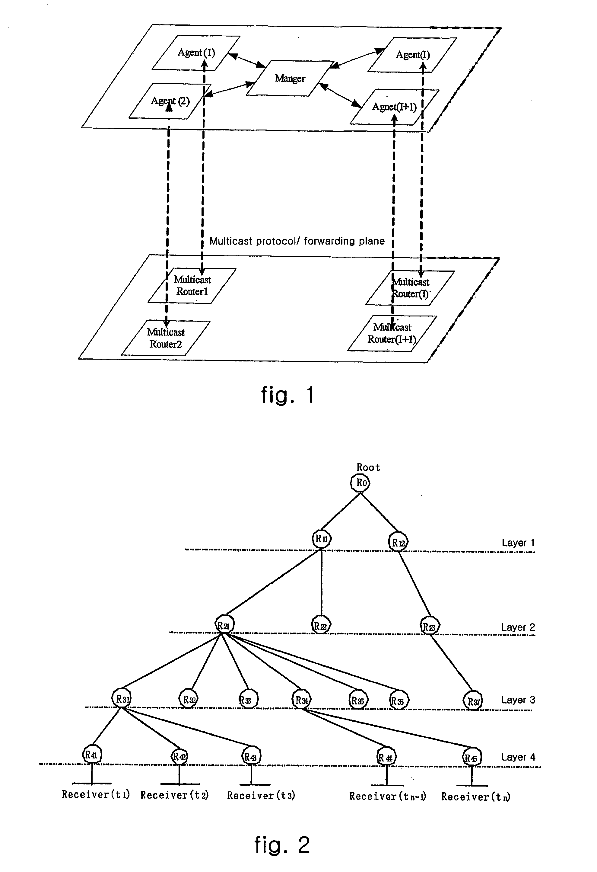
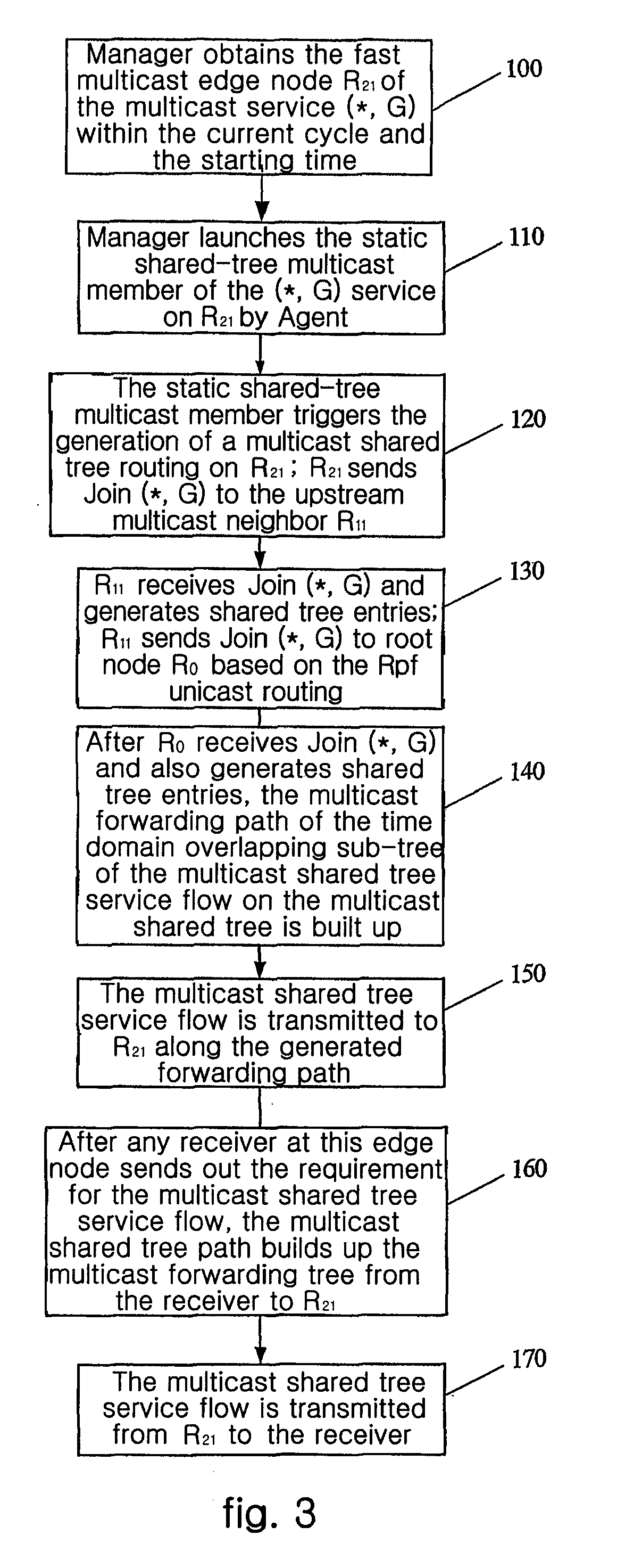
[0054]This embodiment realizes the fast multicast by using a fast multicast system to initiate the static shared tree multicast member Igmp_static_member (*, G) at the fast multicast edge node in the multicast shared tree environment (*, G).

[0055]The fast multicast system mainly comprises two planes, one is multicast protocol and forwarding plane, and the other is fast multicast control plane, as shown in FIG. 1.

[0056]The multicast protocol and forwarding plane is composed of original multicast protocol and forwarding system in multicast network. It performs corresponding operations under the control of fast multicast control plane to realize fast multicast.

[0057]The fast multicast control plane comprises two parts: the management module Manager and the agent module Agent added in the multicast network. Manager exists within the fast multicast management server (it uses the logical definition in the text, and in fact it can be united with routers) and is mainly r...

second embodiment

The Second Embodiment

[0110]The present embodiment realizes fast multicast through the static shared tree multicast member Igmp_static_member (*, G) in multicast source tree environment (S, G). (S,G) environment may not always use static (S, G) member to realize fast multicast, since the network equipments that support (S, G) static multicast member must support SSM, while not all the (S, G) environments support SSM. In this case, the method in present embodiment can be used.

[0111]The present embodiment is similar to the method that the static shared tree multicast member Igmp_static_member (*, G) implements fast multicast in multicast shared tree environment. The differences lie in: (1) the edge node at which the static shared tree multicast member is launched by the fast multicast system is the edge node of the time domain overlapping sub-tree in the multicast source tree; (2) if it is the PIMSM multicast protocol, then it needs to firstly trigger multicast shared tree by the stati...

third example

The Third Example

[0121]fast multicast is implemented in multicast source tree environment (S, G) through the static source tree multicast member Igmp_static_member (S, G).

[0122]The static source tree multicast member Igmp_static_member (S, G) refers to the multicast member that maintain statically the existence of multicast source tree on the interface of a network equipment Router that supports IgmpV3. This multicast member functions the same as the ones that have been generated from IgmpV3 do, and it will always be valid as long as it is not deleted actively. When supporting SSM protocol, the static source tree multicast member can be initiated in advance on the edge node of the time domain overlapping sub-tree of multicast source tree, the existence of the multicast tree from the root node of multicast source tree to said edge node is triggered and maintained by said multicast member, and the multicast source tree service flow can be transmitted to said edge node in advance.

[0123...


PUM


Abstract

The present invention discloses a method for implementing fast multicast and a system thereof. The system comprises multicast protocol, forwarding plane and fast multicast control plane, and the fast multicast control plane further comprises management module and agent module. The method comprises steps of: determining an edge node of time domain overlapping sub-tree of corresponding multicast tree in the multicast service according to the analysis of time domain; initiating the static multicast member of multicast service on said edge node, so that an interface at which the static multicast member is initiated generates a requirement for multicast service; generating the multicast overlapping sub-tree from said edge node to a multicast root node, so that the multicast service flow is transmitted to said edge node in advance; after sending out the requirement for the multicast service flow through any receiver at said edge node, multicast tree path establishes a multicast forwarding tree from the receiver to the edge node, the multicast service flow will be transmitted from this edge node to the receiver. The present invention can effectively reduce the delay of multicast application.

Description

TECHNICAL FIELD[0001]The present invention refers to a multicast system and the realization of multicast in a network.TECHNOLOGY BACKGROUND[0002]The multicast technology effectively solves the problem of “single-point sending & multi-points receiving” and realizes efficient point-to-multipoint data transmission in the network and therefore highly saves network bandwidth and reduces network load. As a communication method that is parallel to unicast and broadcast, the significance of multicast is not limited thereto. What's more, by utilizing multicast characteristics of the network, it can conveniently offer some new value-added services (VAS) , including Internet information services such as live online, digital TV, network TV, distance learning, telemedicine, network radio station and real-time video conference, and the like.[0003]As regards to routing equipments, the network multicast protocols mainly include intra-domain multicast protocol such as PIMSM, PIMDM, DVMRP and the lik...

Claims


Application Information

Patent Timeline
Patent Type & Authority Applications(United States)
IPC IPC(8): H04L12/56H04L45/16
CPCH04L12/18H04L45/64H04L45/48H04L45/16
Inventor HUANG, JINHONGWANG, MINGYIKONG, YONGWU, BO
Owner ZTE CORP
Learn More