Overexposure correction for large volume reconstruction in computed tomography apparatus

a computed tomography and overexposure correction technology, applied in the field of medical imaging, can solve the problems of unsatisfactory correction algorithm for so-called 3d large volume image acquisition, affect the use of 3d imaging that uses 2d, and affect the detection of low contrast objects, etc., to achieve good contrast resolution, improve the quality of reconstructed images, and reduce the effect of artifact levels

Inactive Publication Date: 2010-10-07
SIEMENS AG
View PDF10 Cites 5 Cited by
  • Summary
  • Abstract
  • Description
  • Claims
  • Application Information

AI Technical Summary

Benefits of technology

[0016]The present invention provides an over-exposure correction method and system which is suited for three-dimensional large-volume image acquisitions using multiple imaging passes, but can also be used for standard 3D acquisitions that are obtained, for example, by a single pass image acquisition. The present method and system provides good contrast resolution, together with low artifact levels, and thereby provides a substantial improvement in the reconstructed image quality.

Problems solved by technology

A dynamic range of 14 bits is often not large enough to avoid over-exposure in 2D projection images obtained by the multi-axis system, which has a negative impact on 3D imaging that use the 2D projection images because the reconstructed density values (Hounsfield values) are too small.
In addition to the over-exposure problem, one encounters so-called capping artifacts, for example even for a homogeneous object.
Capping artifacts hinder or eliminate the possibility of detecting low contrast objects in the reconstructed images.
However, the correction algorithm is not ideal for so-called 3D large volume image acquisitions which can be done with the Artis Zeego system (a robotic imaging system) and which is performed using two independent image runs.
The currently used over-exposure correction algorithm has problems dealing with this asymmetry in the imaging process and as a result creates artifacts at the edges of the object of interest.

Method used


Image

  • Overexposure correction for large volume reconstruction in computed tomography apparatus
  • Overexposure correction for large volume reconstruction in computed tomography apparatus
  • Overexposure correction for large volume reconstruction in computed tomography apparatus

Examples


Embodiment Construction

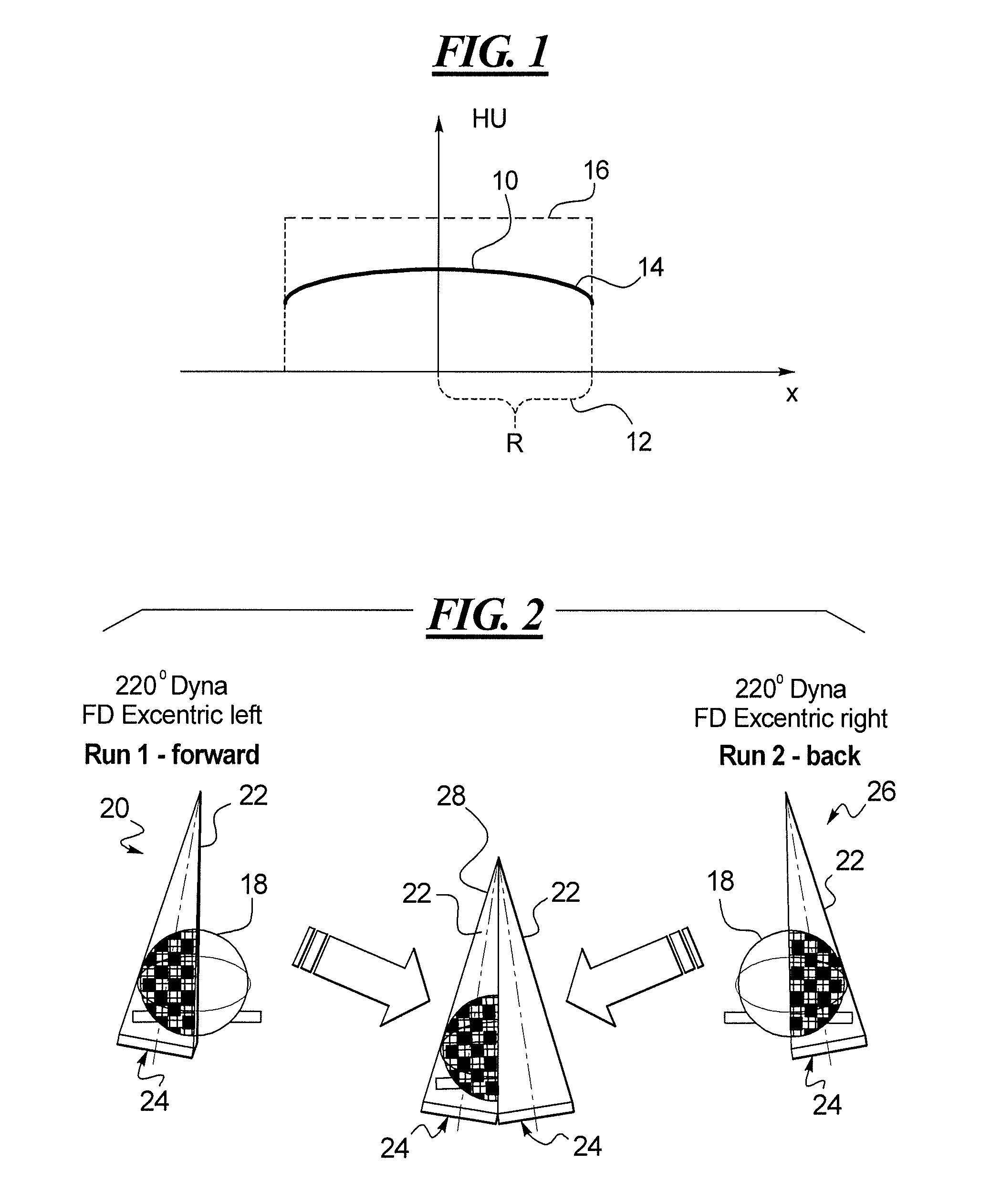
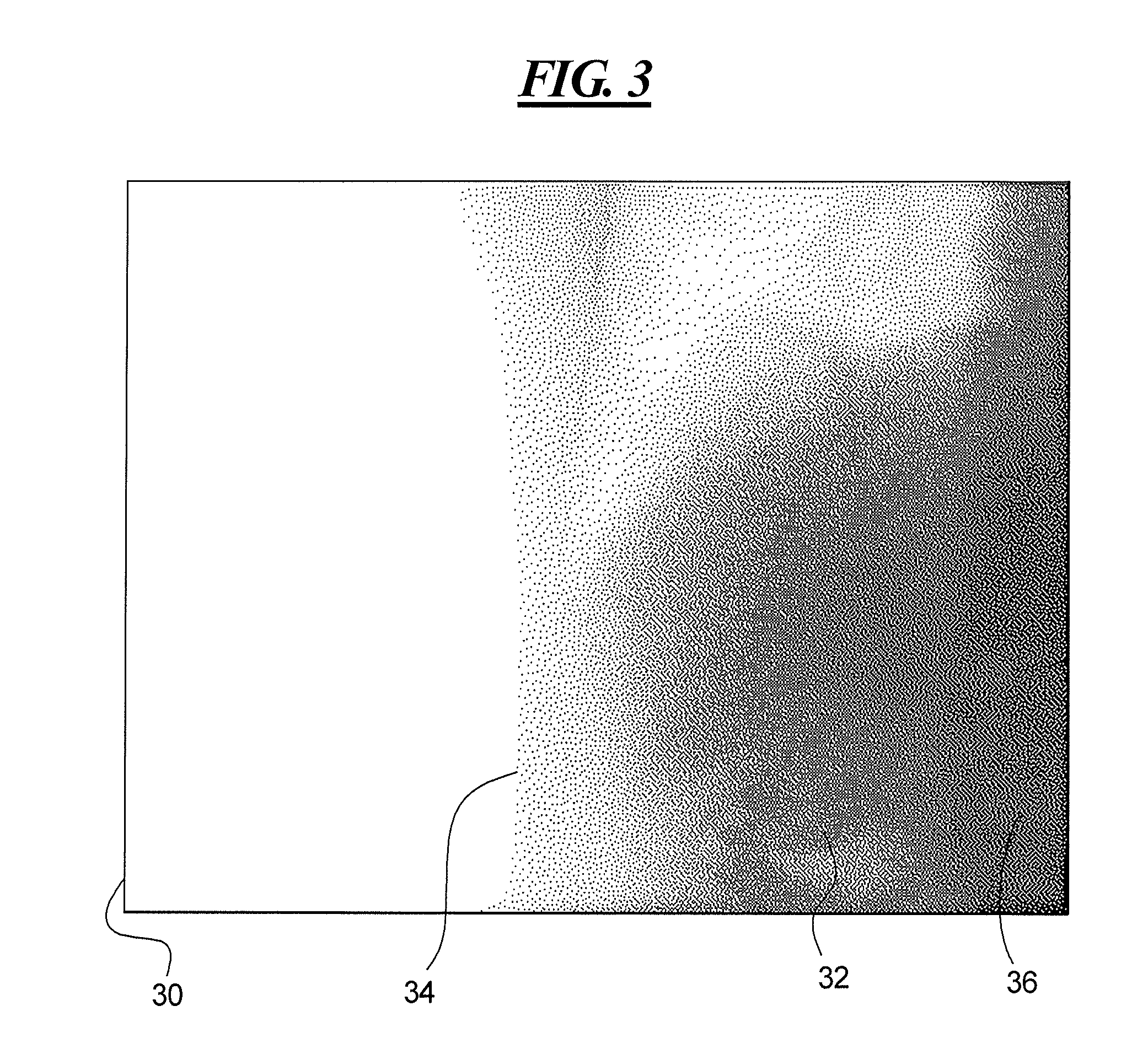
[0033]There is shown in FIG. 1 a graph showing capping effects at the edges of a projection image, as described in greater detail above. FIG. 2 is a schematic illustration of two pass imaging process for imaging a large volume object, as described above. FIG. 3 is an X-ray image of one side of a human torso showing that the left side of the image is lighter than the right side, as described above. FIG. 4 is an image slice of a reconstructed three-dimensional image obtained by two-dimensional projection imaging in two passes, as described in the foregoing.

[0034]Over-exposure correction according to the present method and system is determined according to an algorithm. The algorithm is performed by a programmed computer device or system. The algorithm uses values illustrated in FIG. 5. An object to be imaged is represented by a gray shaded oval that has a density μ({right arrow over (r)}). The intensity of the imaging beam is Io as shown by arrow 54 and a detector 56 is operable to se...


PUM


Abstract

A method and system of processing medical images such as projection images of large volume structures obtained by two-pass scanning for generating three-dimensional images. Measured values of each image frame is calculated as an image line. Over-exposed portions of the image line are detected to at one end of the image line and then at the other end of the image line. A determination is made of the approximate center of the image line. A line integral of the image line is generated and then using an assumed shape the over-exposed portions are extrapolated. The processed image frames may then be combined to generate the three-dimensional image.

Description

CROSS-REFERENCE TO RELATED APPLICATION[0001]This application claims the benefit of U.S. Provisional Patent Application Ser. No. 61 / 165,787, filed Apr. 1, 2009, which is incorporated by reference herein.BACKGROUND OF THE INVENTION[0002]1. Field of the Invention[0003]The present invention relates generally to method and apparatus for medical imaging, and more particularly to a method and apparatus for exposure compensation in a computed tomography imaging system.[0004]2. Description of the Related Art[0005]In medical imaging systems, a detector is used to detect signals generated by a signal source so that a medical image of a patient is obtained from the detected signals. Multi-axis imaging systems provide multiple axis positioning and movement of the signal source and signal detector in the imaging system. An example of a multi-axis imaging system is the Artis multi-axis medical imaging system of Siemens AG. The Artis multi-axis system uses an FD (Flat Detector technology) detector ...

Claims


Application Information

Patent Timeline
IPC IPC(8): G06K9/00
CPCG06T11/00
Inventor BRUNNER, THOMASSCHREIBER, BERND
Owner SIEMENS AG
Why Eureka
Try Eureka