
Method of manufacturing disk drive device for reducing adhesive amount of particles, and disk drive device manufactured by the method

a technology of adhesive particles and manufacturing methods, which is applied in the direction of cleaning using liquids, instruments, record information storage, etc., can solve the problems of thermal asperity failure, head crash failure can become a serious problem, and the accuracy of reading the reproduced signal to be deteriorated, so as to improve the cleaning level and reduce the probability of occurrence of ta failure.

Inactive Publication Date: 2010-10-07
SAMSUNG ELECTRO MECHANICS JAPAN ADVANCED TECHNOLOGY CO LTD
View PDF9 Cites 10 Cited by
  • Summary
  • Abstract
  • Description
  • Claims
  • Application Information

AI Technical Summary

Benefits of technology

[0010]Accordingly, the present invention has been made to solve the aforementioned problems, and a purpose of the invention is to provide a technique in which the cleanness level of a component of a disk drive device can be improved and in which the possibility of the occurrence of a TA failure can be maintained at a low level even when the flying height of a magnetic head is small.
[0012]According to the embodiment, the component is subjected to an ultrasonic wave cleaning while in purified water, using ultrasonic waves of at least two frequencies. The ultrasonic waves to be used are selected from the frequencies of, for example, approximately 40 KHz to 200 KHz. In this case, a relatively low frequency is used as a first ultrasonic wave frequency. When a frequency is low, the wavelength is long and strong cavitation can occur, allowing for large mass particles to be removed efficiently. A relatively high frequency is used as a second frequency thereof. When a frequency is high, the wavelength is short, allowing for particles remaining in narrow spaces to be removed efficiently by the short wavelength. That is, large particles having a large mass, and small particles having a small mass and remaining in narrow spaces can be removed efficiently by performing the ultrasonic wave cleaning using ultrasonic waves of at least two (high and low) frequencies, allowing the cleanness level of the whole component to be enhanced. Further, the assembly work is carried out in the assembly process, continuous from the cleaning process, in a clean area having a predetermined cleanness level or a greater level of cleanness without moving the component to another area after the cleaning, and hence the assembly of the disk drive device can be completed in a state where the attachment of particles is suppressed. As a result, the probability of the occurrence of a TA failure can be reduced even when the flying height of the magnetic heads is small.
[0014]Blowing the mixture of purified water and air against the component to be cleaned provides a great amount of kinetic energy for removing particles. Accordingly, large mass particles remaining on the component, which cannot be removed only by the purified water cleaning, can be removed, allowing the cleanness level of the whole component to be enhanced. Further, the assembly work is performed in the assembly process in the clean area having a predetermined cleanness level or a greater level of cleanness without moving the component to another area after the cleaning, and hence the assembly of the disk drive device can be completed in a state where the reattachment of particles is suppressed. As a result, the probability of the occurrence of a TA failure can be reduced even when the flying height of the magnetic heads is small.
[0016]According to the embodiment, the assembly of a disk drive device can be performed with components whose cleanness levels are enhanced by the cleaning process. As a result, the probability of the occurrence of a TA failure can be reduced even when the flying height of the magnetic heads is small.

Problems solved by technology

On the other hand, because an MR device is used in an extremely-narrow flying height, the occurrence of thermal asperity failure (hereinafter, referred to as “TA failure”) or head crash failure can become a serious problem.
TA failure is caused due to momentary heat generation in the MR device, the heat generation triggered by kinetic energy generated by the contact of the MR device with a minute foreign substance on the surface of the disk while the flying magnetic head traces the recording tracks.
When the MR device is momentarily heated followed by being cooled, the resistance value of the MR device momentarily varies such that a reproduced signal is superimposed with a noise, causing the accuracy of reading the reproduced signal to be deteriorated.
In a manufacturing method using the aforementioned batch cleaning, the level of the cleanness as a whole by the cleaning process is generally low.
Also, particles once detached from a part to be cleaned may likely to adhere to another part.
Further, when intending to obtain a desired cleanness level, the cleaning takes a long time, causing the working efficiency to be deteriorated.
As stated above, if many particles remain on the parts, TA failure is more likely to occur when the flying height of the magnetic head is small, becoming an obstacle for obtaining a higher density and an increased capacity of the disk drive device.
Accordingly, it can be thought that a process of wiping the particles off with, for example, a solvent such as hexane, could be added before or after the assembly work; however, the addition of the process causes a decrease in the manufacturing efficiency, and, in many cases, the particles cannot be removed thoroughly with the wiping process.

Method used


Image

  • Method of manufacturing disk drive device for reducing adhesive amount of particles, and disk drive device manufactured by the method
  • Method of manufacturing disk drive device for reducing adhesive amount of particles, and disk drive device manufactured by the method
  • Method of manufacturing disk drive device for reducing adhesive amount of particles, and disk drive device manufactured by the method

Examples


Embodiment Construction

[0024]The invention will now be described by reference to the preferred embodiments. This does not intend to limit the scope of the present invention, but to exemplify the invention.

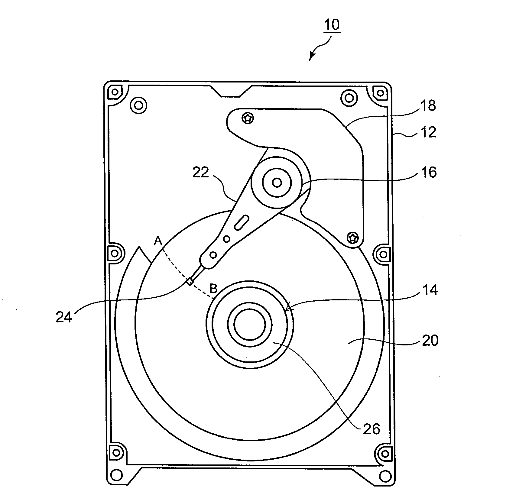
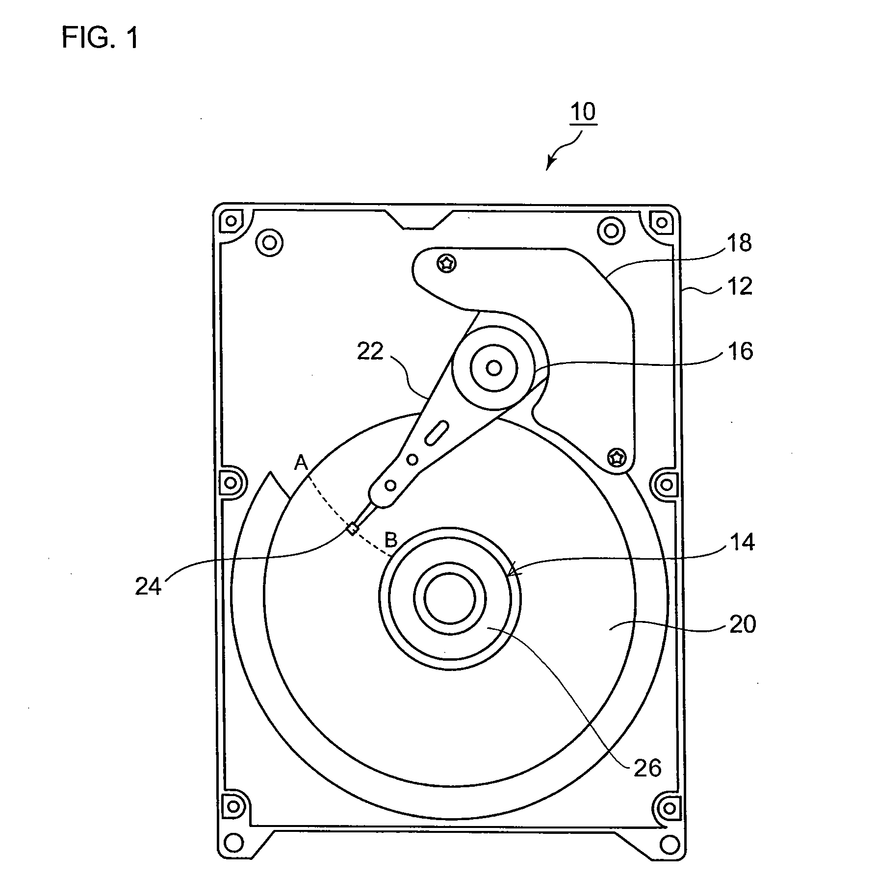
[0025]Hereafter, preferred embodiments of the present invention will be described based on the accompanying drawings. FIG. 1 is a view illustrating the internal structure of a hard disk drive (HDD) 10, an example of a disk drive device assembled by using components manufactured by a manufacturing method according to the present embodiment (hereinafter, simply referred to as a “disk drive device 10”). It is noted that FIG. 1 illustrates a state where the cover of the device is removed to expose the internal structure.

[0026]A brushless motor 14, an arm bearing unit 16, a voice coil motor 18, etc., are mounted on the top surface of a base member 12. The brushless motor 14 supports, on the rotation axis thereof, a hub member 26 on which a recording disk 20 is mounted, allowing the recording disk 20 on which ...


PUM

PropertyMeasurementUnit
sizeaaaaaaaaaa
pHaaaaaaaaaa
flying heightaaaaaaaaaa

Abstract

In a method of manufacturing a disk drive device, a cleaning process and an assembly process are performed in succession in a clean room having a predetermined cleanness level. The cleaning process includes an alkali cleaning process, a first purified water cleaning process, a second purified water cleaning process, a spray cleaning process, a draining process and a drying process. In the first purified water cleaning process, purified water ultrasonic wave cleaning is sequentially performed on the base member of the disk drive device to be cleaned by using ultrasonic waves of frequencies of 40 kHz, 68 kHz and 132 kHz in purified water filled in a first purified water cleaning tank. The cleaned base member and other components having a predetermined cleanness level are assembled in the assembly process continuous from the cleaning process.

Description

BACKGROUND OF THE INVENTION[0001]1. Field of the Invention[0002]The present invention relates to a method of manufacturing a disk drive device and a disk drive device manufactured by the method, and in particular, to a method of manufacturing a disk drive device for reducing the adhesive amount of particles and a disk drive device manufactured by the method.[0003]2. Description of the Related Art[0004]Recently, the rotational accuracy of disk drive devices, such as HDDs and the like, has been dramatically improved by providing them with a fluid dynamic bearing unit. With this improvement, a disk drive device has been required to have a higher density and a more increased capacity. For example, a disk drive device magnetically storing data rotates a recording disk with recording tracks at high speed so that a read / write operation of data is executed while the flying magnetic head of the device is tracing the recording tracks with a slight flying height between both of them. In order ...

Claims


Application Information

Patent Timeline
Patent Type & Authority Applications(United States)
IPC IPC(8): G11B5/10B08B3/12
CPCY10T29/49002Y10T29/49025G11B33/1446Y10T29/49027G11B5/012
Inventor NISHIHARA, KENJI
Owner SAMSUNG ELECTRO MECHANICS JAPAN ADVANCED TECHNOLOGY CO LTD
Learn More