
Direct feed/effluent heat exchange in fluid catalytic cracking

Active Publication Date: 2010-09-30
UOP LLC
View PDF1 Cites 9 Cited by
  • Summary
  • Abstract
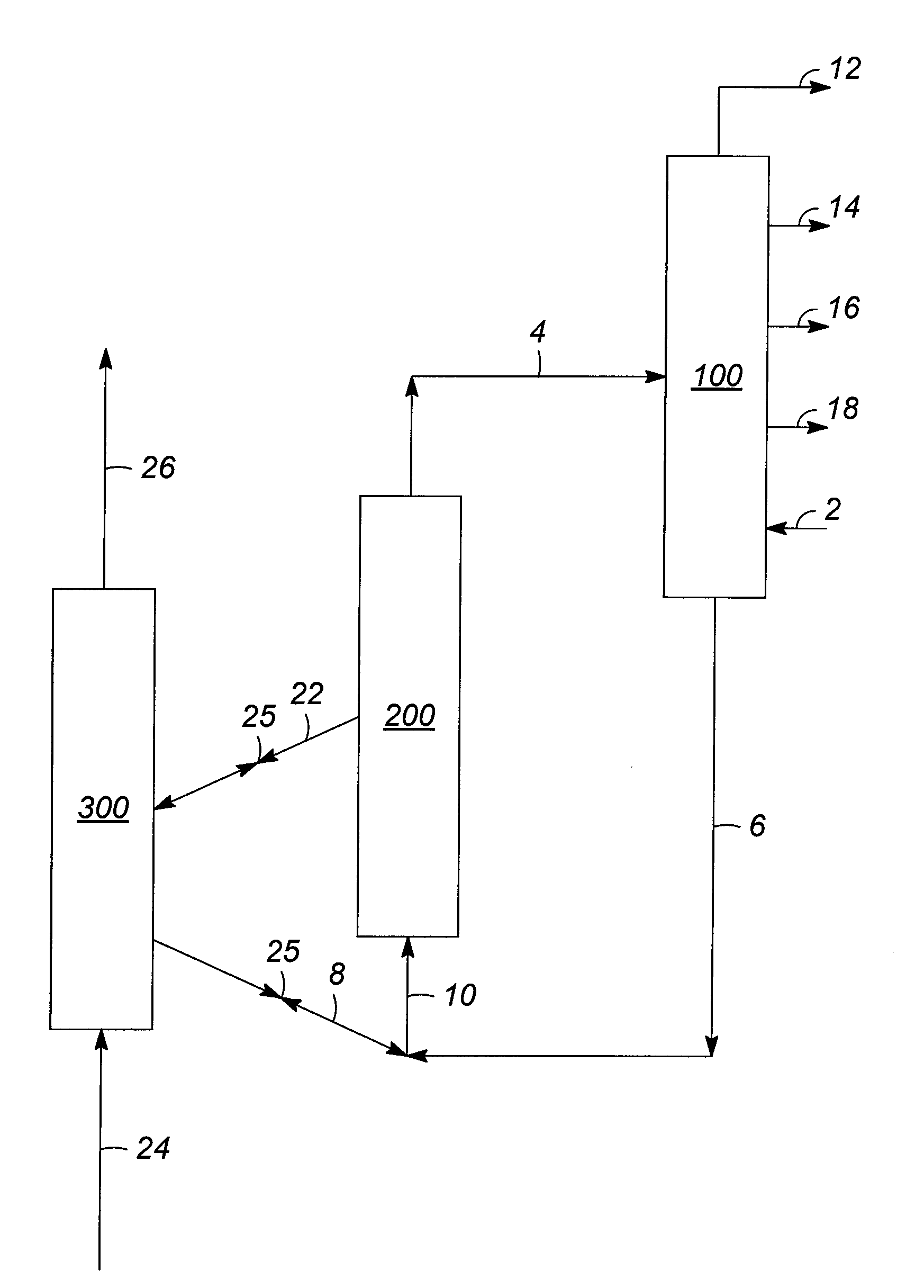
  • Description
  • Claims
  • Application Information

AI Technical Summary

Benefits of technology

[0006]Aspects of the invention are associated with the discovery of methods for exploiting, in fluid catalytic cracking (FCC) processes, the characteristics of hydroprocessed hydrocarbon feeds or other hydrocarbon feed streams having reduced amounts of coke precursors. In particular, such feeds having a low coking tendency can be processed using FCC with direct reactor feed / reactor effluent heat exchange to improve the yield of desired products such as gasoline boiling range hydrocarbons, while also reducing coke yield and utility requirements. Moreover, hydrocarbon feed streams including hydroprocessed hydrocarbons can be sufficiently upgraded in an FCC reaction zone such that amounts of heavy cycle oil and other conventional FCC reaction products containing hydrocarbons boiling above about 343° C. (650° F.) are significantly reduced or even eliminated.
[0007]Direct FCC reactor feed / reactor effluent heat exchange optimizes thermal efficiency and may be conveniently carried out in the main fractionating column (i.e., main column), which is downstream of the FCC reaction zone and used to fractionate and recover reaction products (e.g., fuel gas, C3 / C4 hydrocarbons, gasoline boiling range hydrocarbons, and light cycle oil). Such direct heat exchange can advantageously satisfy much of the heat input required for the FCC hydrocarbon feed stream to attain the desired reaction temperature in the FCC reaction zone and consequently reduce the quantity of heat required from coke combustion in the FCC catalyst regeneration zone. Direct heat exchange similarly satisfies much of the heat removal requirement for cooling superheated FCC reactor effluent vapors in a “desuperheating” section of the FCC main column.
[0010]An additional advantage associated with the fluid catalytic cracking of hydroprocessed hydrocarbon streams or other hydrocarbon feed streams having a low coking tendency (i.e., a reduced level of one or more coke precursors), utilizing direct reactor feed / reactor effluent heat exchange as discussed above, is improved efficiency FCC catalyst regeneration, through the use of oxygen-enriched regeneration gas. In particular, the reduced amounts of catalyst coke obtained with such hydrocarbon feeds can be combusted in an environment having a higher oxygen content, relative to air or other gases fed conventionally to FCC catalyst regenerators. The higher oxygen content beneficially increases the combustion temperature of the solid, regenerated catalyst and consequently the amount of heat transferred back into the FCC reaction zone. The regeneration of conventional, spent FCC catalyst, having a relatively greater quantity of deposited coke, normally requires air or another oxygen-containing gas with a significant quantity of inert gases (e.g., nitrogen) to prevent excessive combustion temperatures and possibly damage to the catalyst and / or regenerator equipment. In contrast, according to various embodiments of the invention, representative catalyst regeneration gas streams introduced into the FCC regeneration zone have an oxygen content of at least 90% by volume, thereby diminishing the amount of nitrogen and / or other inert gases present, which act as a heat sink. Reduced catalyst coke generation, coupled with increased regeneration gas oxygen concentration, allows the FCC operation with higher quality (e.g., hydroprocessed) hydrocarbon feed streams to be improved in terms of its low overall coke yield and increased liquid product yields.

Problems solved by technology

Despite these advantages of direct heat exchange, conventional FCC technology cannot readily adopt this mode of operation.
Direct heat exchange is problematic due to the net generation of high boiling hydrocarbon products, normally recovered in the main column bottoms, which pass to the FCC reaction zone together with the hydrocarbon feed.
The processing of such a feed stream would involve the same, significant drawbacks of FCC processes attempting to operate with recycle of the main column bottoms material, namely high catalyst coke production, high regeneration temperatures, and reduced product yields.

Method used


Image

  • Direct feed/effluent heat exchange in fluid catalytic cracking
  • Direct feed/effluent heat exchange in fluid catalytic cracking

Examples


example 1

[0036]Computer modeling was used to predict product yields obtained from fluid catalytic cracking (FCC) using, as a hydrocarbon feed stream, a hydroprocessed hydrocarbon stream. This stream was namely a representative high boiling hydrocarbon fraction obtained from a commercial hydrocracker, at a 10,000 barrels per stream day (BPSD) flow rate. In particular, the model simulated the direct heat exchange between this hydrocarbon feed stream and the FCC effluent in the FCC main column. The simulated main column bottoms stream was a hydrocarbon fraction comprising >95% by volume of hydrocarbons boiling at a temperature of greater than 343° C. (650° F.). According to the yield estimating model, conversion of this stream in the FCC reaction zone provided a greater than 65% by weight yield of a gasoline boiling range hydrocarbon fraction, characterized as C5+ hydrocarbons having a distillation temperature of 193° C. (380° F.) at the 90% recovery point. The simulated regeneration gas stream...


PUM

PropertyMeasurementUnit
Temperatureaaaaaaaaaa

Abstract

Fluid catalytic cracking (FCC) processes are described, in which hydroprocessed hydrocarbon streams or other hydrocarbon feed streams having a low coking tendency are subjected to direct heat exchange with the FCC reactor effluent, for example in the FCC main column. The processes operate with sufficient severity such that little or no net FCC main column bottoms liquid (e.g., with a 343° C. (650° F.) distillation cut point) is generated. Regeneration temperatures with the representative low coking tendency feeds are beneficially increased by using an oxygen-enriched regeneration gas stream.

Description

FIELD OF THE INVENTION[0001]The invention relates to processes for fluid catalytic cracking (FCC) used to upgrade hydrocarbon feed streams and particularly those such as hydroprocessed hydrocarbons having a low coking tendency (i.e., low levels of one or more coke precursors). Representative FCC processes use direct FCC reactor feed / reactor effluent heat exchange in an FCC main column used to fractionate the effluent, combined with an oxygen-rich catalyst regeneration gas stream (e.g., having at least 90% by volume of oxygen).DESCRIPTION OF RELATED ART[0002]There are a number of continuous, cyclical oil refining processes in which a fluidized solid catalyst is contacted with an at least partially liquid phase hydrocarbon stream. In the fluidized contacting or reaction zone, carbonaceous and other fouling materials are deposited on the solid catalyst as coke, which reduces catalyst activity. The catalyst is therefore normally conveyed continuously to another section, namely a rejuven...

Claims


Application Information

Patent Timeline
IPC IPC(8): C10G11/00B01J38/12
CPCC10G11/18C10G69/04C10G2400/02C10G2300/301C10G2300/1033
Inventor LOMAS, DAVID A.VAN OPDORP, PETER J.
Owner UOP LLC
Learn More