Fluid dynamic bearing device
a dynamic bearing and fluid technology, applied in sliding contact bearings, instruments, record information storage, etc., can solve the problems of inability to obtain the dimensional accuracy necessary for the hub, the fluidity of the molten resin is further deteriorated, and the thickness of the metal portion is decreased, so as to improve the fixation accuracy therebetween, the effect of reducing the risk of deformation
- Summary
- Abstract
- Description
- Claims
- Application Information
AI Technical Summary
Benefits of technology
Problems solved by technology
Method used
Image

Examples
first embodiment
[0063]In the following, the present invention is described with reference to drawings.
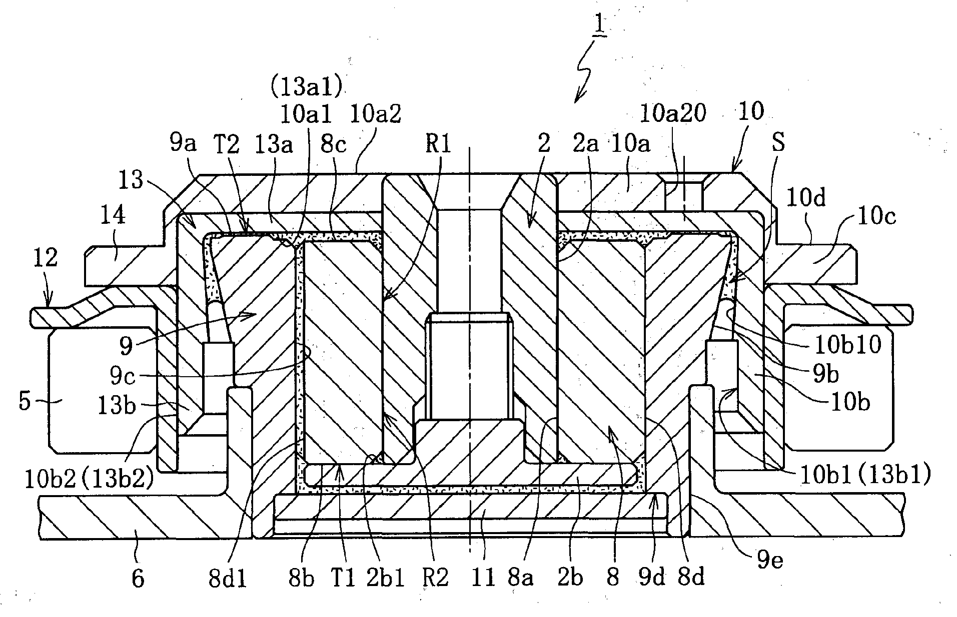
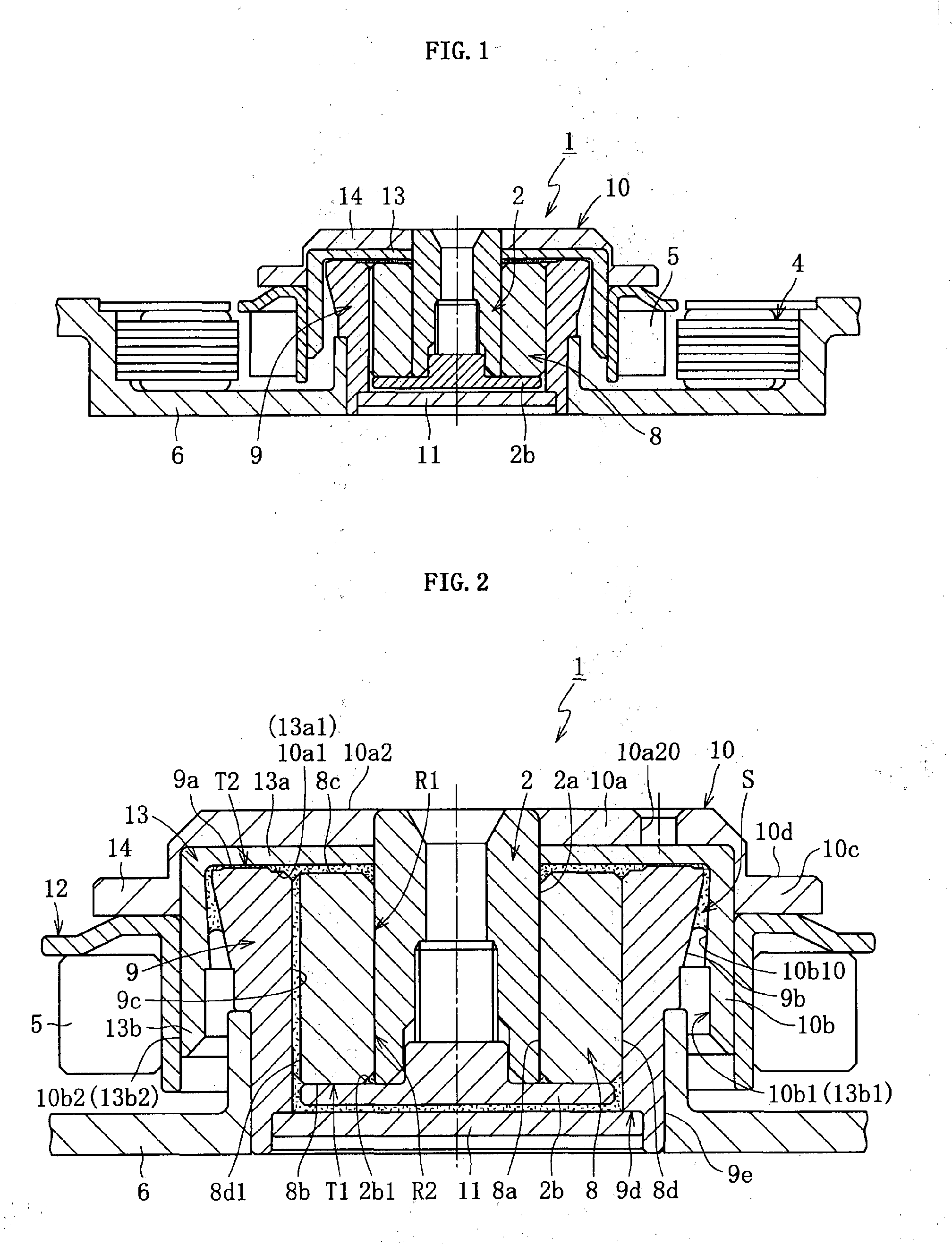
[0064]FIG. 1 conceptually illustrates a construction example of a spindle motor for an information apparatus incorporating a fluid dynamic bearing device 1 of the present invention. The spindle motor is used for a disk drive such as an HDD, and includes the fluid dynamic bearing device (fluid dynamic bearing device) 1 for relatively rotating and supporting a shaft member 2 in a non-contact manner, a stator coil 4 and a rotor magnet 5 opposed to each other through an intermediation of, for example, a radial gap, and a bracket 6. The stator coil 4 is mounted to an inner peripheral surface on the outer peripheral surface side of the bracket 6, and the rotor magnet 5 is fixed on the radially outer side of a hub 10 through an intermediation of a yoke 12. The fluid dynamic bearing device 1 is fixed to the inner periphery of the bracket 6. Further, one or multiple disks as information recording media (not...
second embodiment
[0090]Next, the present invention is described with reference to FIGS. 11 to 17.
[0091]FIG. 11 conceptually illustrates a construction example of a spindle motor for an information apparatus incorporating a fluid dynamic bearing device 201 of the present invention. This spindle motor is used for a disk drive such as an HDD, and includes the fluid dynamic bearing device 201 for relatively rotating and supporting a shaft member 202 in a non-contact manner, a stator coil 204 and a rotor magnet 205 opposed to each other through an intermediation of, for example, a radial gap, and a bracket 206. The stator coil 204 is mounted to an inner peripheral surface 206a on the outer peripheral surface side of the bracket 206, and the rotor magnet 205 is fixed to the outer periphery of the hub 203. The fluid dynamic bearing device 201 is fixed to the inner periphery of the bracket 206. Further, one or multiple disks as information recording media (not shown) are held on the hub 203. In the spindle ...
third embodiment
[0122]Next, the present invention is described with reference to FIGS. 18 to 27.
[0123]FIG. 18 conceptually illustrates a construction example of a spindle motor for an information apparatus incorporating a fluid dynamic bearing device (fluid dynamic bearing device) 301 of the present invention. The spindle motor is used for a disk drive such as an HDD, and includes the fluid dynamic bearing device 301 for relatively rotating and supporting a shaft member 302 and a hub 310 in a non-contact manner, a stator coil 304 and a rotor magnet 305 opposed to each other through an intermediation of, for example, a radial gap, and a bracket 306. The stator coil 304 is mounted to an inner peripheral surface on the outer peripheral surface side of the bracket 306, and the rotor magnet 305 is fixed to a yoke 312 provided on the radially outer side of a hub 310. The fluid dynamic bearing device 301 is fixed to the inner periphery of the bracket 306. Further, one or multiple disks as information reco...
PUM
 Abstract
Description
Claims
Application Information
 - R&D
- Intellectual Property
- Life Sciences
- Materials
- Tech Scout
- Unparalleled Data Quality
- Higher Quality Content
- 60% Fewer Hallucinations
Browse by: Latest US Patents, China's latest patents, Technical Efficacy Thesaurus, Application Domain, Technology Topic, Popular Technical Reports.
© 2025 PatSnap. All rights reserved.Legal|Privacy policy|Modern Slavery Act Transparency Statement|Sitemap|About US| Contact US: help@patsnap.com