Eureka AIR delivers breakthrough ideas for toughest innovation challenges, trusted by R&D personnel around the world.

D-shaped cross section l.e.d. based light

a technology of led light and cross section, which is applied in the direction of semiconductor devices for light sources, lighting and heating apparatus, lighting support devices, etc., can solve problems such as disassembly problems

Inactive Publication Date: 2010-09-02
ILUMISYS
View PDF101 Cites 319 Cited by
  • Summary
  • Abstract
  • Description
  • Claims
  • Application Information

AI Technical Summary

Benefits of technology

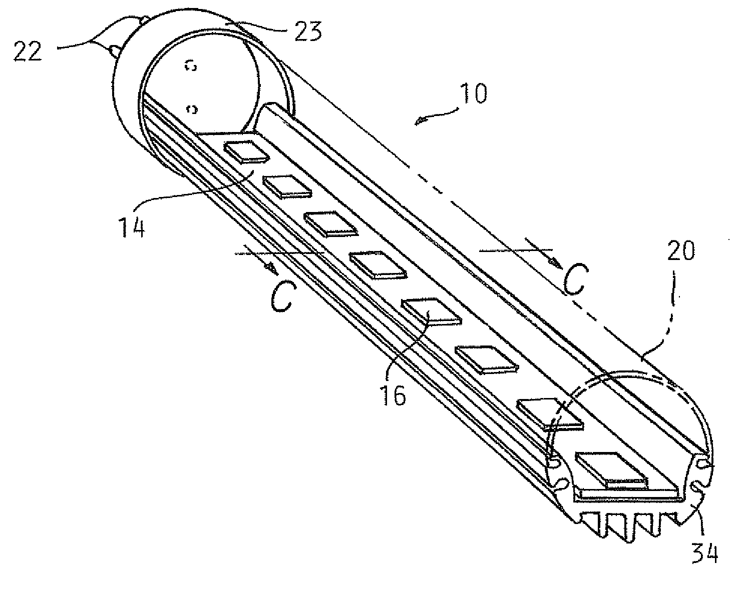
[0005]Disclosed herein are embodiments of LED-based lights for replacing a conventional fluorescent light bulb in a fluorescent light fixture. One such embodiment comprises an elongate housing having a D-shaped cross section with a flat base with opposing longitudinal edges, opposing sides extending generally perpendicular to the flat base from the opposing longitudinal edges, and a curved surface spanning the opposing sides opposite the flat base. The light also comprises multiple LEDs; a circuit board structure defining a LED-mounting side and a primary heat transferring side opposite the LED-mounting side, the multiple LEDs mounted on the LED-mounting side at predetermined intervals along a length of the circuit board for emitting light through the curved surface of the elongate housing. At least one electrical connector is at a longitudinal end of the tubular housing in electrical communication with the circuit board.
[0006]Another embodiment of a replacement light for a conventional fluorescent tube light usable in a conventional fluorescent fixture comprises a generally tubular body forming the outer surface of the light over substantially its entire length, the tubular body having a D-shaped cross section with a flat base with opposing longitudinal edges, opposing sides extending generally perpendicular to the flat base from the opposing longitudinal edges, and a curved surface spanning the opposing sides opposite the flat base. A circuit board structure is disposed within the tubular body along the flat base and thermally joined thereto while being electrically insulated therefrom. A pair of end caps is disposed on the opposite ends of the tubular body and carrying bi-pin connectors. An array of LEDs is arranged longitudinally along the circuit board and thermally bon

Problems solved by technology

Although conventional fluorescent bulbs have certain advantages over, for example, incandescent lights, they also pose certain disadvantages including, inter alia, disposal problems due to the presence of toxic materials within the glass tube.

Method used


Image

  • D-shaped cross section l.e.d. based light
  • D-shaped cross section l.e.d. based light
  • D-shaped cross section l.e.d. based light

Examples


Embodiment Construction

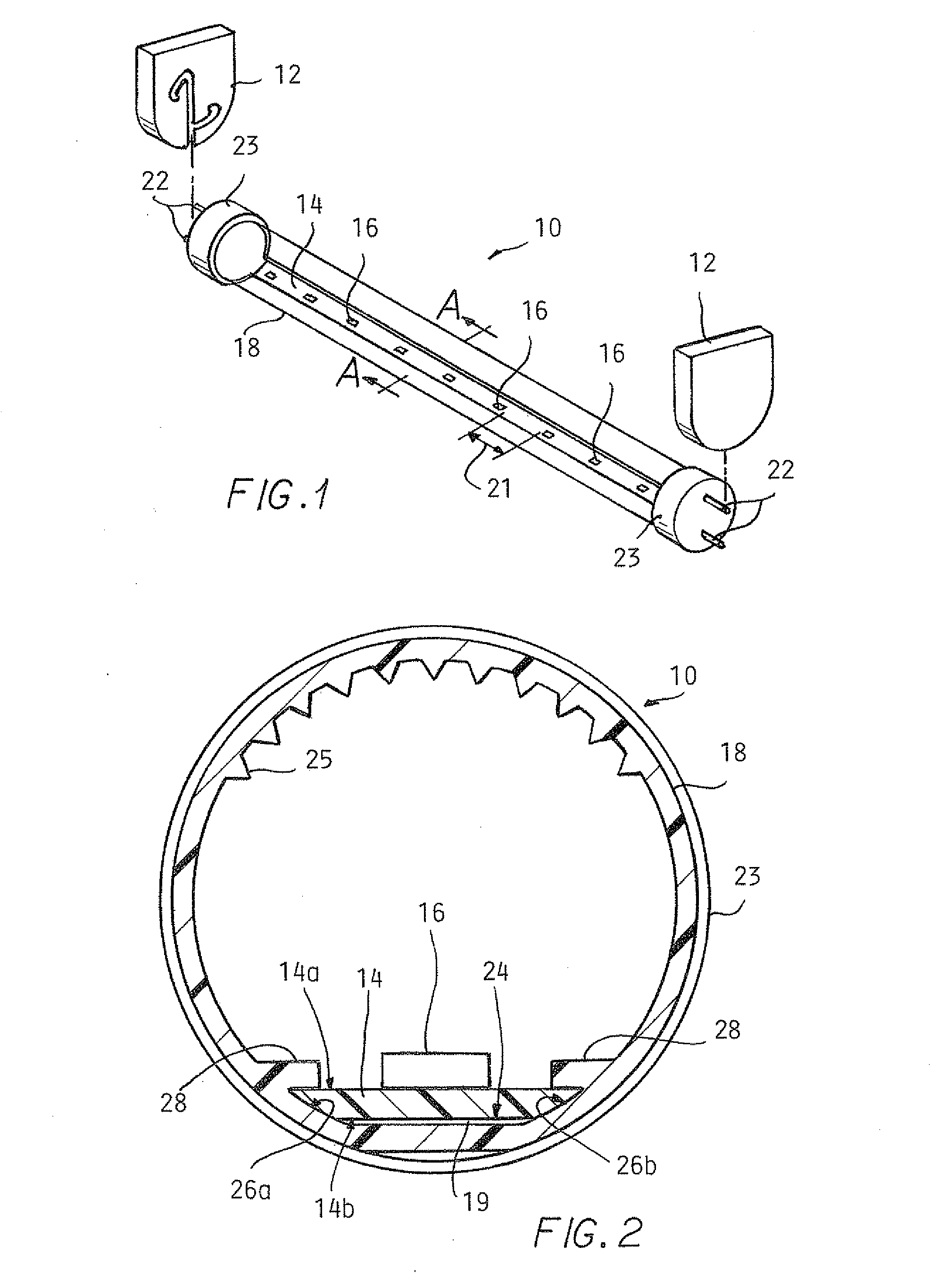
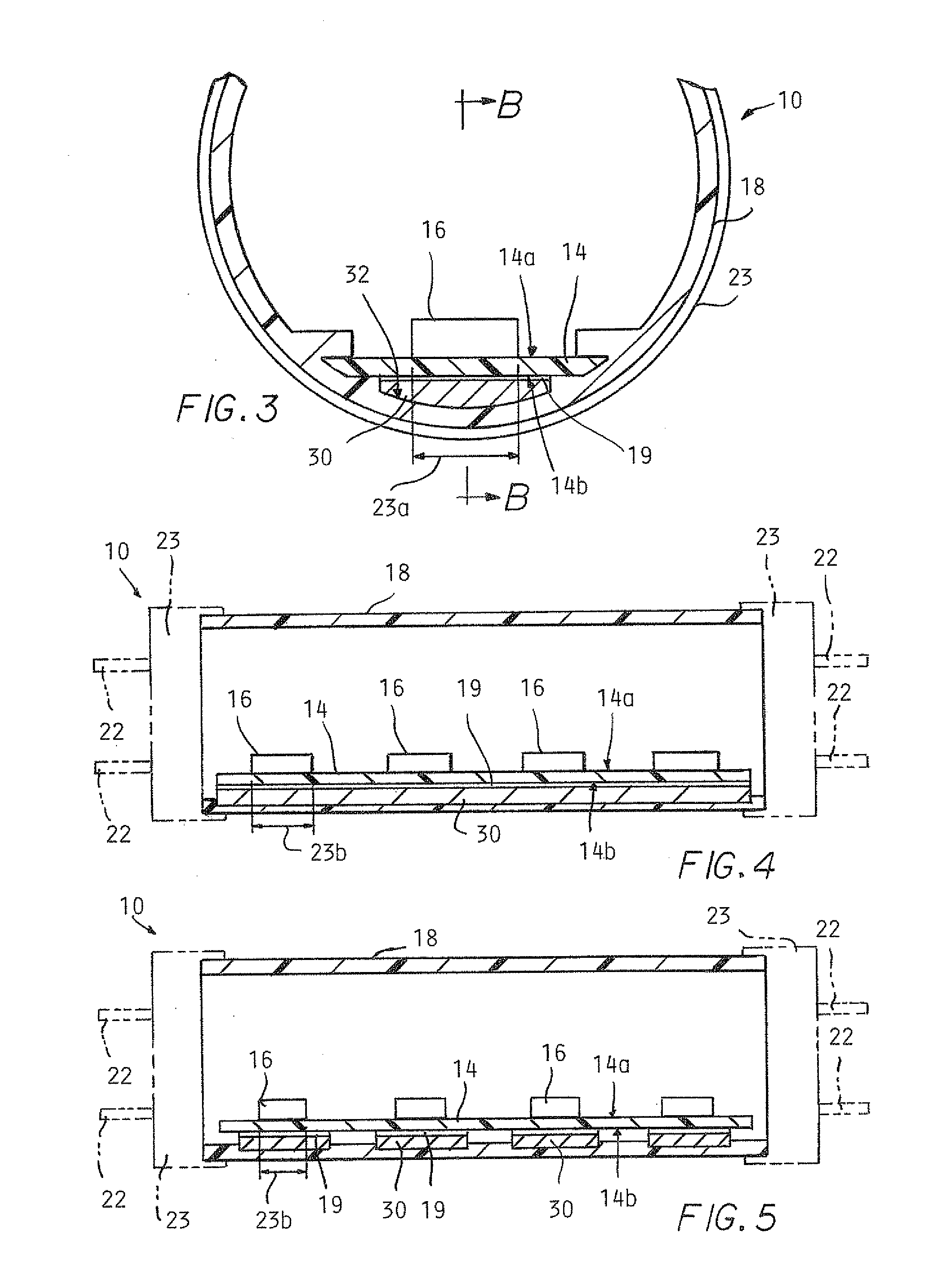
[0023]FIGS. 1-10 illustrate LED-based replacement lights 10 according to the present invention for replacing a conventional fluorescent light bulb in a fluorescent fixture 12. The lights 10 each include a circuit board 14, multiple LEDs 16, a tubular housing at least partially defined by a high-dielectric translucent portion, and bi-pin electrical connectors 22 affixed to plastic end caps 23.

[0024]FIGS. 1 and 2 show an illustrative embodiment of the present invention in which the tubular housing consists of a tube 18. The circuit board 14 has a LED-mounting side 14a and a primary heat transferring side 14b opposite the LED-mounting side 14a. The circuit board 14 may be made in one piece or in longitudinal sections joined by electrical bridge connectors. The circuit board 14 and the tube 18 are in thermally conductive relation with the circuit board 14 attached to the tube 18 using highly thermally conductive adhesive transfer tape 19. The circuit board 14 can alternatively be positi...


PUM


Abstract

A LED-based replacement light for a fluorescent socket is constructed such that a tubular housing has a D-shaped cross section with a flat base with opposing longitudinal edges, opposing sides extending generally perpendicular to the flat base from the opposing longitudinal edges, and a curved surface spanning the opposing sides opposite the flat base. A circuit board structure defines a LED-mounting side with multiple LEDs mounted on the LED-mounting side at predetermined intervals along a length of the circuit board, with at least areas of a primary heat transferring side directly underlying the respective LEDs in thermally conductive relation with the tubular housing for highly electrically insulated thermal transmission of heat generated by the multiple LEDs from the circuit board to an ambient environment surrounding an exterior of the tubular housing. At least one electrical connector is at a longitudinal end of the housing in electrical communication with the circuit board.

Description

CROSS-REFERENCE TO RELATED APPLICATION[0001]This application is a continuation-in-part of U.S. patent application Ser. No. 12 / 126,579, filed May 23, 2008, the entire contents of which is incorporated herein by reference.TECHNICAL FIELD[0002]The present invention relates to a light emitting diode (LED) based light for replacing a conventional fluorescent light in a fluorescent light fixture.BACKGROUND[0003]Fluorescent tube lights are widely used in a variety of locations, such as schools and office buildings. Although conventional fluorescent bulbs have certain advantages over, for example, incandescent lights, they also pose certain disadvantages including, inter alia, disposal problems due to the presence of toxic materials within the glass tube.[0004]LED-based tube lights which can be used as one-for-one replacements for fluorescent tube lights having appeared in recent years. One such LED-based fluorescent replacement light includes LEDs mounted on an elongated circuit board in a...

Claims


Application Information

Patent Timeline
IPC IPC(8): F21V7/00F21V21/00F21V29/00
CPCF21K9/17F21Y2101/02F21Y2103/003F21V29/763F21V29/507F21V29/74F21V29/75Y02B20/386F21V7/0058F21K9/27F21Y2103/10F21Y2115/10Y02B20/30
Inventor IVEY, JOHNAMRINE, JAMES
Owner ILUMISYS
Why Eureka
Eureka Blog
Learn More