
Peritoneal Dialysis Methods and Apparatus

a technology of peritoneal dialysis and apparatus, applied in the field of peritoneal dialysis, can solve problems such as the possibility of processing fluids

Active Publication Date: 2010-08-26
RGT UNIV OF CALIFORNIA +1
View PDF18 Cites 123 Cited by
  • Summary
  • Abstract
  • Description
  • Claims
  • Application Information

AI Technical Summary

Benefits of technology

The present invention provides a system for removing toxins from the peritoneal cavity of a person or animal through the use of a portable or wearable dialysis unit. The system separates the fluid with a relatively protein-rich stream and a relatively protein-free stream, with the protein-rich stream being regenerated and reintroduced into the peritoneal cavity. The separation is facilitated by using a higher percentage of urease, an enzyme that is immobilized on a substrate with greater than Van der Waals forces. The system also includes a sorbent system that removes toxins and middle molecule uremic toxins from the relatively protein-rich stream. The processing line can include a sterilizer and a gas extractor for safety and efficiency. The relatively protein-free stream can be treated simply as waste, or used for other purposes such as the addition of nutrients or medications. The system is portable and wearable, with the dry weight of the entire processing line being no more than 5 kg for portable and no more than 1 kg for wearable systems.

Problems solved by technology

Previous systems, including our own, utilized urease which was not adequately immobilized, which meant that only a very small fraction (e.g. 2-3%) of the fluid could be processed as protein-rich fluid, and that most of the fluid reintroduced into the user was derived from the protein free portion.

Method used


Image

  • Peritoneal Dialysis Methods and Apparatus
  • Peritoneal Dialysis Methods and Apparatus
  • Peritoneal Dialysis Methods and Apparatus

Examples


Embodiment Construction

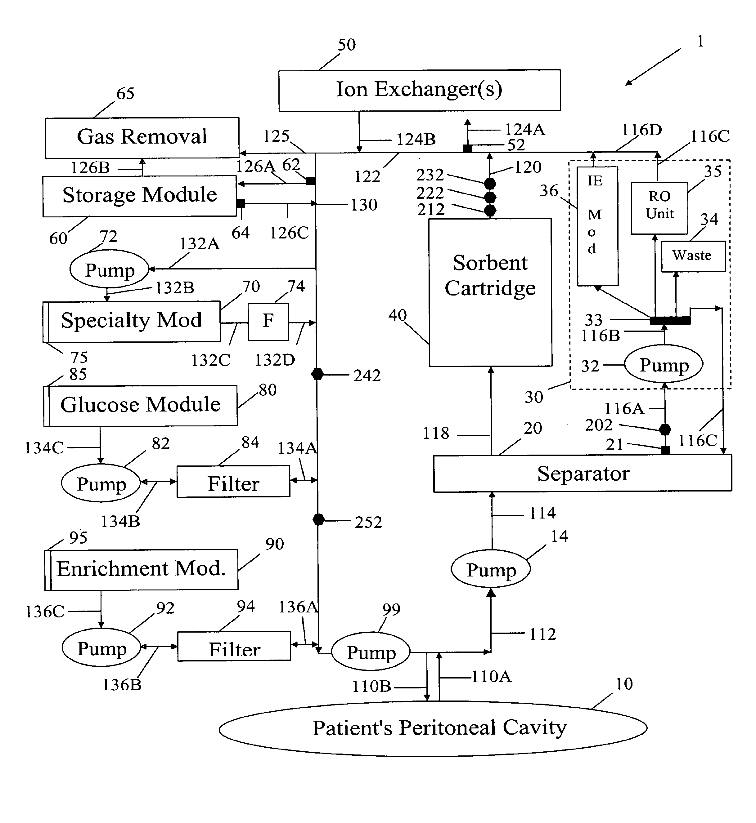
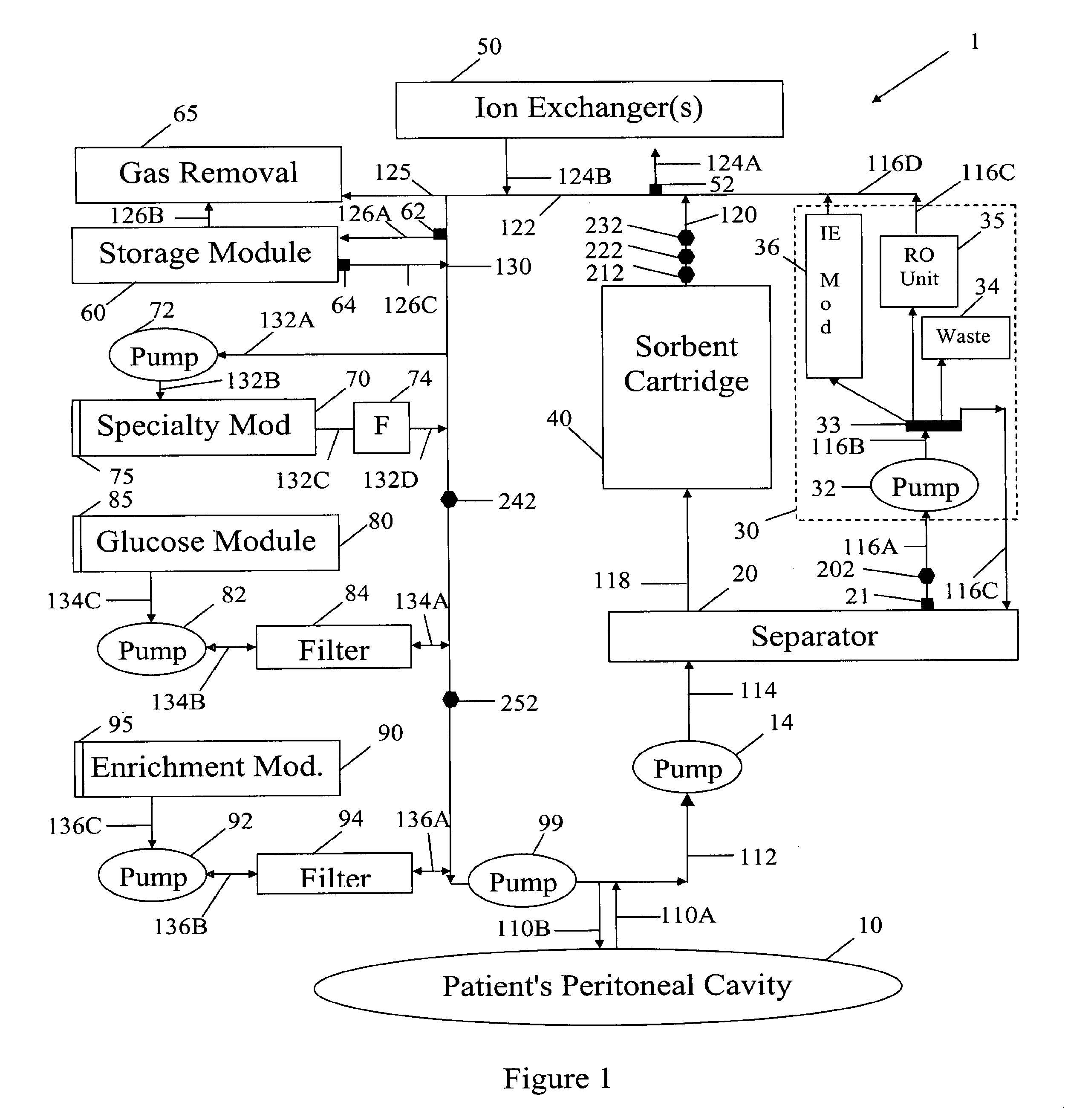
[0049]In FIG. 1 spent peritoneal fluid is withdrawn from a user / patient's peritoneal cavity 10 through catheter 110A, and processed along a processing line that includes a separator 20, an ultrafiltrate handling assembly 30, a sorbent assembly 40, and one or more ion exchangers 50, optional storage module 60, a specialty module 70, a glucose module 80, and an enrichment module 90. The fluid is then pumped back into the peritoneal cavity through in-flowing catheter 110B by pump 99. All of the components of FIG. 1, minus the catheters 110A, 110B and the peritoneal cavity 10 are sometimes referred to herein as artificial kidney 1.

[0050]Catheters 110A, 110B should be interpreted interactively as either two physically separate catheters, or a single catheter with one or more lumens. All of the catheters, the various pumps 14, 32, 72, 82, 92 and 99, and the various fluid conduits 112, 114, 116A, 116B, 116C, 116D, 118, 120, 122, 124A, 124B, 126A, 126B, 126C, 130, 132A, 132B, 132C, 132D, 13...


PUM


Abstract

A peritoneal-based (“bloodless”) artificial kidney processes peritoneal fluid without need for additional fluids (“waterless”). Fluid is separated into a protein-rich stream and a protein-free stream. The protein-rich stream is regenerated using a sorbent assembly, and its protein composition can be modified by removal of selected protein(s) (“dialysate-pheresis”). It is then reconstituted with additives and returned into the peritoneal cavity, thereby reducing protein-loss and providing oncotic-pressure for ultrafiltration. The protein-free stream is used to produce free water, and an alkaline or acid fluid for optimization of the composition of the regenerated stream. The unused protein-free stream can be used to “reverse flush” the separator to maintain its patency and the excess discarded for fluid-balance regulation. Compared to prior art, immobilization of urease allows more protein rich fluid to be regenerated and re-circulated into the peritoneal cavity for toxin removal and allows practicable development of portable and wearable artificial kidneys.

Description

[0001]This application claims priority to our copending U.S. provisional patent applications with the Ser. Nos. 60 / 763,254 and 60 / 763,337, both filed Jan. 30, 2006, and which are incorporated by reference herein.FIELD OF THE INVENTION[0002]The field of the invention is peritoneal dialysis.BACKGROUND[0003]Patients with inadequate kidney function require either dialysis or kidney transplantation for survival. When successful, kidney transplantation is the most ideal form of treatment since it restores continuous kidney function and returns patients to normal or near-normal life. However, the major problems in transplantation are the increasing shortage of donor kidneys relative to the expanding number of patient's with end-stage kidney failure, and the deterioration of the function of the transplant from causes including rejection, chronic (transplant) allograft nephropathy and the recurrence of the original kidney disease. There is also the life-long requirement for multiple medicati...

Claims


Application Information

Patent Timeline
Patent Type & Authority Applications(United States)
IPC IPC(8): A61M1/28
CPCA61M1/28A61M1/1696A61M1/1686
Inventor ROBERTS, MARTINLEE, DAVID B.N.
Owner RGT UNIV OF CALIFORNIA
Learn More