
Flexible materials for optical applications

a flexible material and optical technology, applied in the field of flexible materials for optical applications, can solve the problems of limited number of possible combinations of layers, porous layers, brittle inorganic layers mentioned above, etc., and achieve the effect of high mechanical flexibility

Inactive Publication Date: 2010-08-19
WIFAG POLYTPE HLDG AG
View PDF6 Cites 76 Cited by
  • Summary
  • Abstract
  • Description
  • Claims
  • Application Information

AI Technical Summary

Benefits of technology

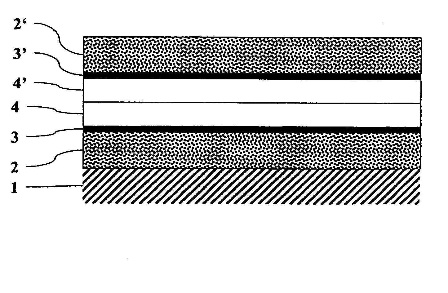
[0030]Accordingly it is an objective of the invention to provide flexible materials for optical applications, composed of a flexible support and at least two layers in direct contact, having a big difference of their refractive indices, on said support. These materials have a high mechanical flexibility and may be manufactured in a cost-efficient manner in high quantities.

Problems solved by technology

However, the number of possible combinations of layers is limited by the restricted compatibility of the compounds and the feasible coating technologies.
All these inorganic layers mentioned above are brittle and have only a very restricted mechanical flexibility.
The porous layers mentioned before, used in optical applications, also do not have the required mechanical properties and, further, unsuitable steps are sometimes necessary in manufacture (high temperature treatment, supercritical drying etc.).
They are therefore not suitable for cheap, big-scale manufacture on flexible supports.
The number of realizable combinations of layers is limited, however, also in this case by the restricted compatibility of the compounds (adhesion, solubility in different solvents etc.) and the problem of precise multilayer coating.
The layer thickness may not be below 3 μm, because, otherwise, the required ink absorption properties of the polymer film would not be guaranteed.
The quality of the always present boundary layer between the porous or nanoporous layer and the polymer layer as well as the homogeneity of the polymer layer are not sufficiently good for optical applications.
In recording sheets for ink jet printing, a too sharp boundary layer would be annoying for the reason of undesirable colour effects.

Method used


Image

  • Flexible materials for optical applications
  • Flexible materials for optical applications

Examples


example 1

[0143]A porous or nanoporous layer having a low refractive index and having the composition (in the dry state) as listed in Table 2 was applied to a subbed transparent polyester film Cronar® 742, available from DuPont Teijin Films, Luxemburg.

TABLE 2IngredientQuantity (g / m2)Surface modified SiO26.000Polyvinyl alcohol C1.300Cross-linking agent0.229

[0144]The surface modified SiO2 was prepared according to the method of example 1 of patent application EP 1,655,348.

[0145]Polyvinyl alcohol C is available as Mowiol 40-88 from Omya AG, Oftringen, Switzerland. The cross-linking agent is boric acid, available from Schweizerhall Chemie AG, Basel, Switzerland.

[0146]A non-porous layer with a thickness of about 0.24 μm having a high refractive index and consisting of polyvinyl alcohol B was applied onto this porous or nanoporous layer having a low refractive index.

[0147]Polyvinyl alcohol B is available as Mowiol 56-98 from Omya AG, Oftringen, Switzerland.

example 2

[0148]A porous or nanoporous layer having a low refractive index and having the composition (in the dry state) as listed in Table 3 was applied to the subbed transparent polyester film of Example 1.

TABLE 3IngredientQuantity (g / m2)Surface modified SiO221.052Polyvinyl alcohol C4.928Cross-linking agent0.800

[0149]A non-porous layer having a high refractive index and having the composition (in the dry state) as listed in Table 4 was applied onto this porous or nanoporous layer having a low refractive index.

TABLE 4IngredientQuantity (g / m2)Polyvinyl alcohol D0.070Latex0.930

[0150]Polyvinyl alcohol D is available as Gohsefimer K-210 from Nippon Synthetic Chemical Industry Ltd., Osaka, Japan. The latex is Jonrez E2001, available from MeadWestvaco Corporation, Stamford, USA.

[0151]This layer was sealed at a temperature of 120° C. at a speed of about 27 cm / min with a laminator GBC 3500.

example 3

[0152]A porous or nanoporous layer having a low refractive index and having the composition (in the dry state) as listed in Table 5 was applied to the subbed transparent polyester film of Example 1.

TABLE 5IngredientQuantity (g / m2)Aluminium oxide / hydroxide containing20.250lanthanumLactic acid0.369Polyvinyl alcohol A0.785Polyvinyl alcohol B1.830Cross-linking agent0.021

[0153]The aluminum oxide / hydroxide was prepared according to the method of Example 1 of patent application EP 0,967,086.

[0154]A non-porous layer having a high refractive index and having the composition (in the dry state) as listed in Table 6 was applied onto this porous or nanoporous layer having a low refractive index.

TABLE 6IngredientQuantity (g / m2)Polyvinyl pyrrolidone0.500Cross-linking agent0.250

[0155]Polyvinyl pyrrolidone is available as Luviskol K90 from BASF AG, Wädenswil, Switzerland.

Test Methods

[0156]The flexible material for optical applications according to the invention show well visible interference colors ...


PUM

PropertyMeasurementUnit
Thicknessaaaaaaaaaa
Thicknessaaaaaaaaaa
Thicknessaaaaaaaaaa

Abstract

A flexible material for optical applications in a wavelength range of λ1 to λ2, λ1 being smaller than λ2, composed of a flexible support and at least one multilayer that comprises a porous or nanoporous layer which has a low refractive index and contains inorganic nanoparticles and at least one binder, and a non-porous polymer layer which has a high refractive index and is in direct contact with the porous or nanoporous layer; said flexible material is characterized in that the maximum thicknesses of the boundary layers, in which the refractive index changes from one value to the other and which are located between the porous or nanoporous layers and the non-porous polymer layers that are in direct contact therewith, amount to 0.2 times wavelength λ2; and the difference in the refractive indices of the porous or nanoporous layers and the non-porous polymer layers is at least 0.20, 200 nm and 2500 nm being typical values for λ1 and λ2.

Description

FIELD OF THE INVENTION[0001]The present invention relates to flexible materials for optical applications, composed of a flexible support and, on said support, at least two thin layers in direct contact. The refractive indices of these two layers differ by at least 0.20. One of these layers is porous or nanoporous and contains inorganic nanoparticles, the other layer is a non-porous polymer layer.BACKGROUND OF THE INVENTION[0002]Dielectric thin layers are thin, normally transparent layers consisting of different chemical compounds and typically having layer thicknesses in the micrometer or nanometer range. Dielectric thin layers are used in optical applications in order to change the optical properties of surfaces and boundaries. Incident light is partially reflected and partially transmitted and refracted at such boundaries. The diffraction behavior and the reflection behavior may be efficiently influenced by a suitable choice of materials and layer thicknesses. The thicknesses of i...

Claims


Application Information

Patent Timeline
IPC IPC(8): G02B1/12G02B1/10B05D5/06
CPCG02B1/04G02B5/285G02B1/11
Inventor BEER, ROBERTGUGLER, GILBERTPAUCHARD, MARCSCHUETTEL, STEFAN
Owner WIFAG POLYTPE HLDG AG
Learn More