
Mechanical clamping element and clamping system

a technology of mechanical clamping and clamping elements, which is applied in the direction of screwing, threaded fasteners, manufacturing tools, etc., can solve the problems of locking the nut, difficult to prevent the nut from sliding laterally off the wrench under all conditions, and complicated and cumbersome, so as to achieve the effect of minimal force expenditur

Active Publication Date: 2010-08-05
ZOLLMANN
View PDF13 Cites 16 Cited by
  • Summary
  • Abstract
  • Description
  • Claims
  • Application Information

AI Technical Summary

Benefits of technology

[0004]The invention is directed toward a mechanical clamping element or clamping system with a clamping nut and with a wrench which does not suffer from the disadvantages described above and which makes it possible to clamp a mechanical clamping element reliably without slipping and with minimal expenditure of force.
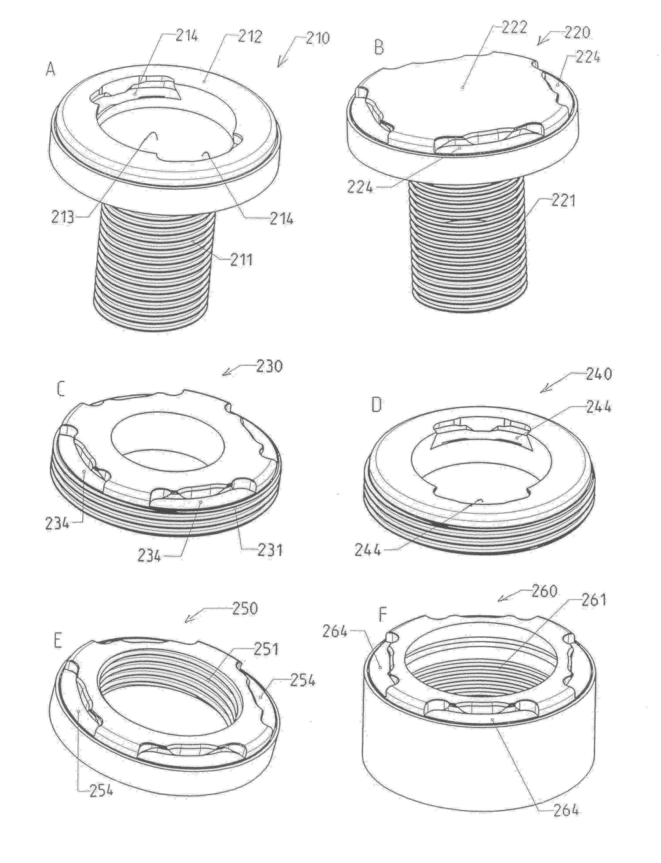
[0005]The inventive clamping system comprises a clamping nut or mechanical clamping element and a wrench for tightening the clamping nut. The clamping nut comprises on one of its end faces at least one and preferably two or more recesses, which are provided to receive projections on the wrench. The recesses are arranged either on the outside edge or on the inside edge of the clamping nut, wherein the opposite edge, that is, the inside edge in the former case or the outside edge in the latter case is closed. As a result, the projections of the wrench can be introduced from the outside or from the inside to engage in the recesses in the clamping nut. The recesses in the inventive clamping nut or of the inventive clamping system are provided with at least one undercut, which can be gripped by the projections of the wrench. This ensures that the wrench will engage without slipping. In particular, the undercut prevents the nut from falling out of the wrench. The closed area of the end face of the clamping nut, whether on the inside edge or on the outside edge, increases the stability of the clamping nut, so that, for example, elevations extending from the end face will not fracture, as happens in the case of clamping nuts according to the prior art. In addition, the closed end face of the clamping nut, whether on the inside or on the outside, prevents the wrench from shifting or slipping laterally or radially out of the recesses.
[0006]In an especially preferred embodiment of the inventive clamping system, the recess has the form of a slot with two narrow sides and two long sides, wherein one of the long sides is closed and one of the long sides is open. In the case of recesses on the outside edge, the outer long side is open, thus corresponding to the outside circumference of the clamping nut. In the case of recesses on the inside edge, the inner long side of the opening is open, thus corresponding to the circumference of the inside edge of the clamping nut. The long side of the recess opposite this open side is provided with at least one undercut. The narrow sides can also comprise one or more undercuts. In an especially preferred embodiment, the narrow sides of the recesses comprise no undercuts; that is, at least part of the edge or inner surface of the narrow sides is perpendicular or at a right angle to the surface of the end face of the clamping nut. In the following, the design of the inner surfaces or inner edges of the recesses is also referred to as the “profile”. The narrow sides of the recesses are the surfaces where the wrench actually makes contact when it tightens or loosens the clamping nut. These are the areas at which torque is transmitted. In comparison to the undercut profiles of these contact surfaces of the known clamping nuts, the flat contact surfaces of the invention make it possible for the projections of the wrench to engage much more effectively during the transmission of force. Torque can therefore be transmitted much more efficiently. As a result of the inventive design of the narrow sides of the recess, furthermore, the surfaces on which the force acts are always engaged with an exact fit, which means that there will be no deformation or digging-in and thus no wear or damage to these contact surfaces.

Problems solved by technology

It is true that, as a result of the undercut profile of the grooves, it is possible to stabilize the nut on the wrench to a certain degree, but it is still impossible to prevent the nut from sliding laterally off the wrench under all conditions.
This separate element for locking the nut, however, is complicated and cumbersome in practice and is therefore not a suitable way of solving the problem.

Method used


Image

  • Mechanical clamping element and clamping system
  • Mechanical clamping element and clamping system
  • Mechanical clamping element and clamping system

Examples


Embodiment Construction

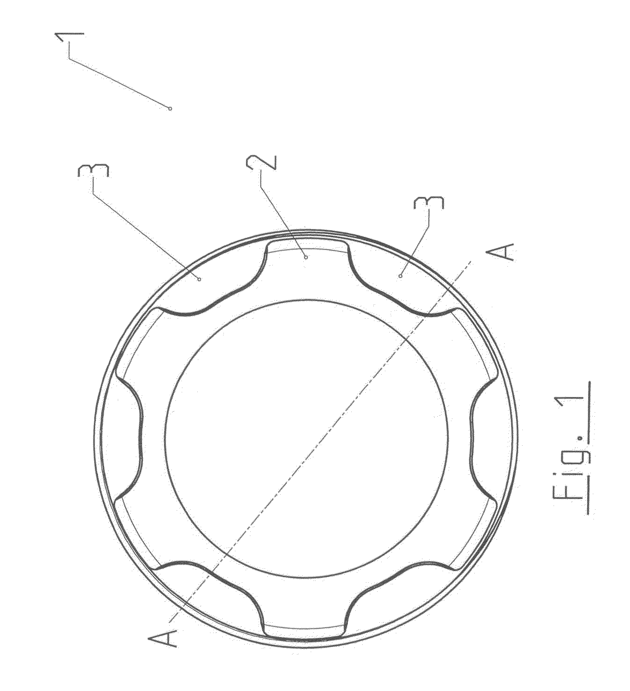
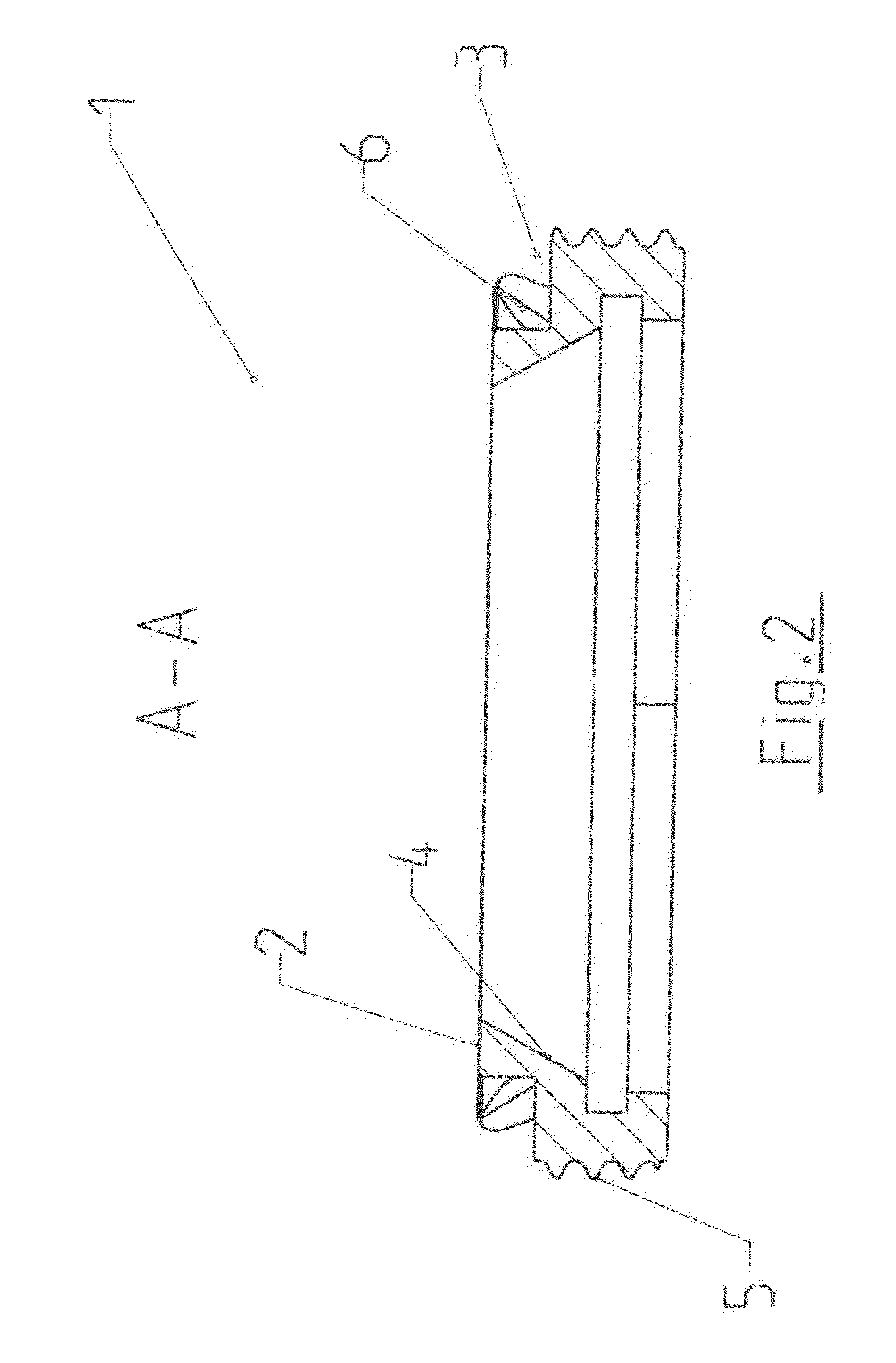
[0040]The top view of an inventive clamping nut 1 in FIG. 1 shows the end Face 2 of the clamping nut with six recesses 3. The recesses 3 are arranged on the outside edge, and the end face 2 is closed on the inside edge. The cross-sectional view along line A-A, shown in FIG. 2, shows an internal cone 4 for the centered gripping of a collet chuck, for example, and an outside thread 5, for example, so that the nut can be screwed into the holder of a machine tool spindle or into a tool holder. The undercut 6 in the profile of the recess 3 can be seen in the cross-sectional view. The end face 2 of the clamping nut 1, which is closed on the inside edge, guarantees the stability of the clamping nut 1, wherein the undercuts 6 in the recesses 3 make it possible for the wrench to engage the nut in a slip-free manner. In addition, the closed inside-edge of the end face 2 prevents the clamping nut from slipping laterally out of the wrench.

[0041]FIG. 3 shows an isometric view of the inventive cl...


PUM

PropertyMeasurementUnit
shapeaaaaaaaaaa
sizeaaaaaaaaaa
areaaaaaaaaaaa

Abstract

A clamping system with a clamping nut and a wrench for tightening the clamping nut, wherein the clamping nut includes at least one recess on either the outside edge or the inside edge of the end face of the clamping nut to receive projections of the wrench. The edge opposite the edge with at least one recess is closed. The at least one recess is provided with at least one undercut, which the projections of the wrench can grip from underneath.

Description

BACKGROUND OF THE INVENTION[0001]The invention pertains to a clamping system with a clamping nut and a wrench for tightening the clamping nut, to a mechanical clamping element, and to the use of an undercut profile.[0002]Various mechanical clamping elements are already known. Clamping nuts are used, for example, to clamp collet chucks, which are used to clamp tool shafts in the tool holder of a machine tool. Especially in cases where space is limited and access to the clamping element is narrow, special measures must be taken to ensure that the necessary force for clamping can be exerted. In the conventional method, clamping is carried out with a wrench, which, for example, is equipped with pins, which engage in hole-like recesses in the clamping nut, so that the wrench can be used to tighten the clamping nut. German Utility Model DE 296 08 677 U1 describes, for example, a clamping nut with slot-like recesses, in which the pins of a wrench can engage.[0003]To prevent the wrench from...

Claims


Application Information

Patent Timeline
Patent Type & Authority Applications(United States)
IPC IPC(8): B23P19/06B25B13/48F16B23/00
CPCF16B23/0007B23B31/201B25B13/48Y10T29/53848F16B23/0061B23B2260/106B25B13/02B25B13/50B23B31/20125
Inventor ZOLLMANN, MARTIN
Owner ZOLLMANN
Learn More