
Electric winding body with optimised performance characteristics and improved protection against overheating

a technology of winding body and electric winding, which is applied in the direction of winding insulation material, plastic/resin/waxes insulators, chemistry apparatus and processes, etc., can solve the problems of material overload, material brittleness, material inability to compensate or absorb this overload, etc., to reduce the occurrence of hot spots, improve the total thermal capacity, and reduce the use of materials. small

Active Publication Date: 2022-11-22
SMARTPOLYMER GMBH
View PDF11 Cites 0 Cited by
  • Summary
  • Abstract
  • Description
  • Claims
  • Application Information

AI Technical Summary

Benefits of technology

The invention provides a type of winding used in electrical machines that has better heat capacity, reduces hotspots, and can balance out if there is too much heat. This helps to prevent damage and keep the machines running safely. It is designed to absorb heat peaks with minimal material use and can be used for both statos and rotors.

Problems solved by technology

A disadvantage of the thermosets is that these have to be cured in an additional operation and the phase transition to the solid phase is irreversible and the materials are very brittle after curing.
If there is excessive thermal stress, these materials cannot compensate for or absorb this overload and are destroyed.
For such winding forms, closed-loop temperature control by adjustment of the current is often not envisaged or not viable.
The problem addressed was that of finding a plastic as insulator that simultaneously offers low shrinkage, high thermal conductivity and flame retardancy.

Method used


Image

  • Electric winding body with optimised performance characteristics and improved protection against overheating

Examples


example 1

without Filling

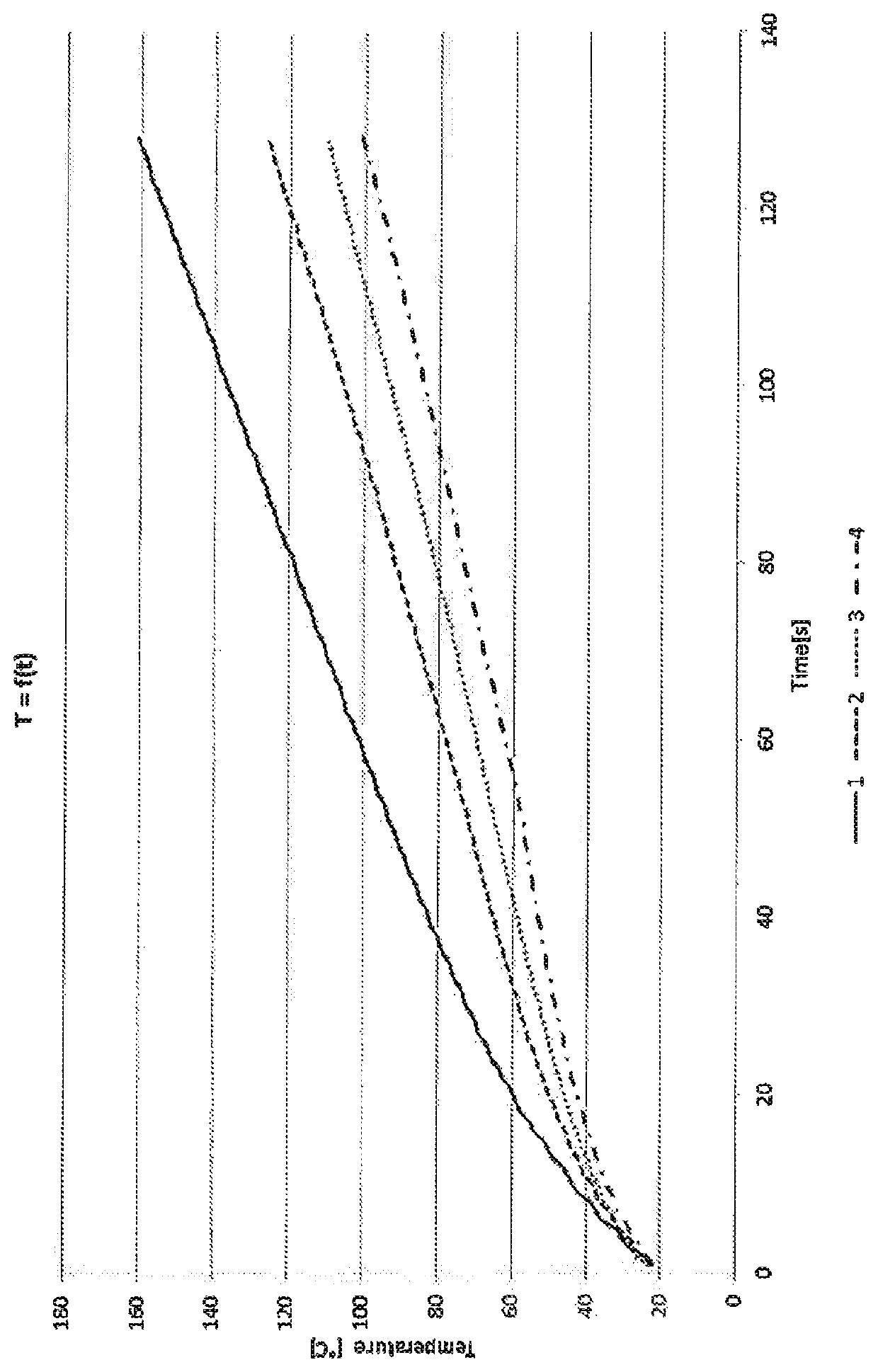
[0021]Using a commercial winding form with copper windings, diameter of copper wire 0.5 mm, length 15 m, without integrated filling, by the test method specified above, the temperature-dependent change in resistance is measured and the temperature is calculated. The result of the measurement is shown in FIGURE 1, curve 1 (no filling). This curve serves for comparative purposes.

example 2

with PE

[0022]A free-flowing PE from LyondellBasell (LUPOLEN® 1800S) is integrated into the coil according to example 1, the weight of which has been determined beforehand, by the method of dipping or spraying. For this purpose, the coil, prior to the filling, is heated to a temperature of 120° C. and, after the filling, kept in a heated chamber at 140° C. for 30 min, and then cooled down to room temperature. As a result, the copper windings and all cavities in the windings are covered with the PE in a form-fitting manner. By measuring the weight of the coil after the dipping or spraying, the amount of PE that has penetrated into the windings of the coil is determined. The mass is 4 g. Then the change in temperature is determined by the method described above. The result of the measurement is shown in FIGURE 1, curve 2 (with PE).

example 3

with PE and Graphite

[0023]A PE from LyondellBasell (LUPOLEN® 1800S) is filled with 20% graphite (SC20O, from Kropfmühl). The free-flowing PE is integrated into the coil according to example 1, the weight of which has been determined beforehand, by the method of dipping or spraying and heat treatment according to example 2. By measuring the weight of the coil after the dipping or spraying, the amount of PE that has penetrated into the windings of the coil is determined. The mass is 4 g. Then the change in temperature is measured by the method described above. The result of the measurement is shown in FIGURE 1, curve 3 (PE+graphite).


PUM

PropertyMeasurementUnit
melt flow indexaaaaaaaaaa
temperatureaaaaaaaaaa

Abstract

The invention relates to an electric winding body which has improved performance characteristics as a result of being impregnated with a thermoplastic material filled with phase change material. These performance characteristics relate to improved heat dissipation, vibration damping, fixing of the coils, and improved protection against overheating by utilizing the sensitive and latent heat storage properties when the polymer units transition from the semi-crystalline state into the amorphous state.

Description

CROSS-REFERENCE TO RELATED APPLICATIONS[0001]This application is being filed under 35 U.S.C. § 371 as a National Stage Application of pending International Application No. PCT / EP2018 / 053945 filed Feb. 16, 2018, which claims priority to the following parent application: German Patent Application No. 10 2017 001 547.3, filed Feb. 17, 2017. Both International Application No. PCT / EP2018 / 053945 and German Patent Application No. 10 2017 001 547.3 are hereby incorporated by reference herein in their entirety.FIELD OF THE INVENTION[0002]The invention relates to an electrical winding form which has improved use properties through impregnation with a thermoplastic material filled with phase change material. These use properties relate to improved dissipation of heat, vibration damping, fixing of the windings, and improved protection from overheating by exploitation of the sensible and latent heat storage properties at the transition from the semicrystalline state of the polymer units to the a...

Claims


Application Information

Patent Timeline
Patent Type & Authority Patents(United States)
IPC IPC(8): H01F5/06C08L25/06C09K5/06H01B3/28H01B3/44H01F27/32H02K3/30H02K5/24H02K15/12
CPCH01F5/06C08L25/06C09K5/063H01B3/28H01B3/441H01B3/442H01F27/327H02K3/30H02K5/24H02K15/12
Inventor REDLINGSHÖFER, BENJAMINGEISSENHÖNER, MARTINSCHACHE, HANNESRIEDE, SABINE
Owner SMARTPOLYMER GMBH
Learn More