
Injection head for an apparatus for the production of a twin-wall pipe

a technology of injection head and twin-wall pipe, which is applied in the direction of tubular articles, domestic applications, other domestic articles, etc., can solve the problems of large amount of injection head, and risk of operation malfunction, so as to reduce the amount of effort required

Active Publication Date: 2020-03-10
HEGLER RALPH PETER
View PDF19 Cites 1 Cited by
  • Summary
  • Abstract
  • Description
  • Claims
  • Application Information

AI Technical Summary

Benefits of technology

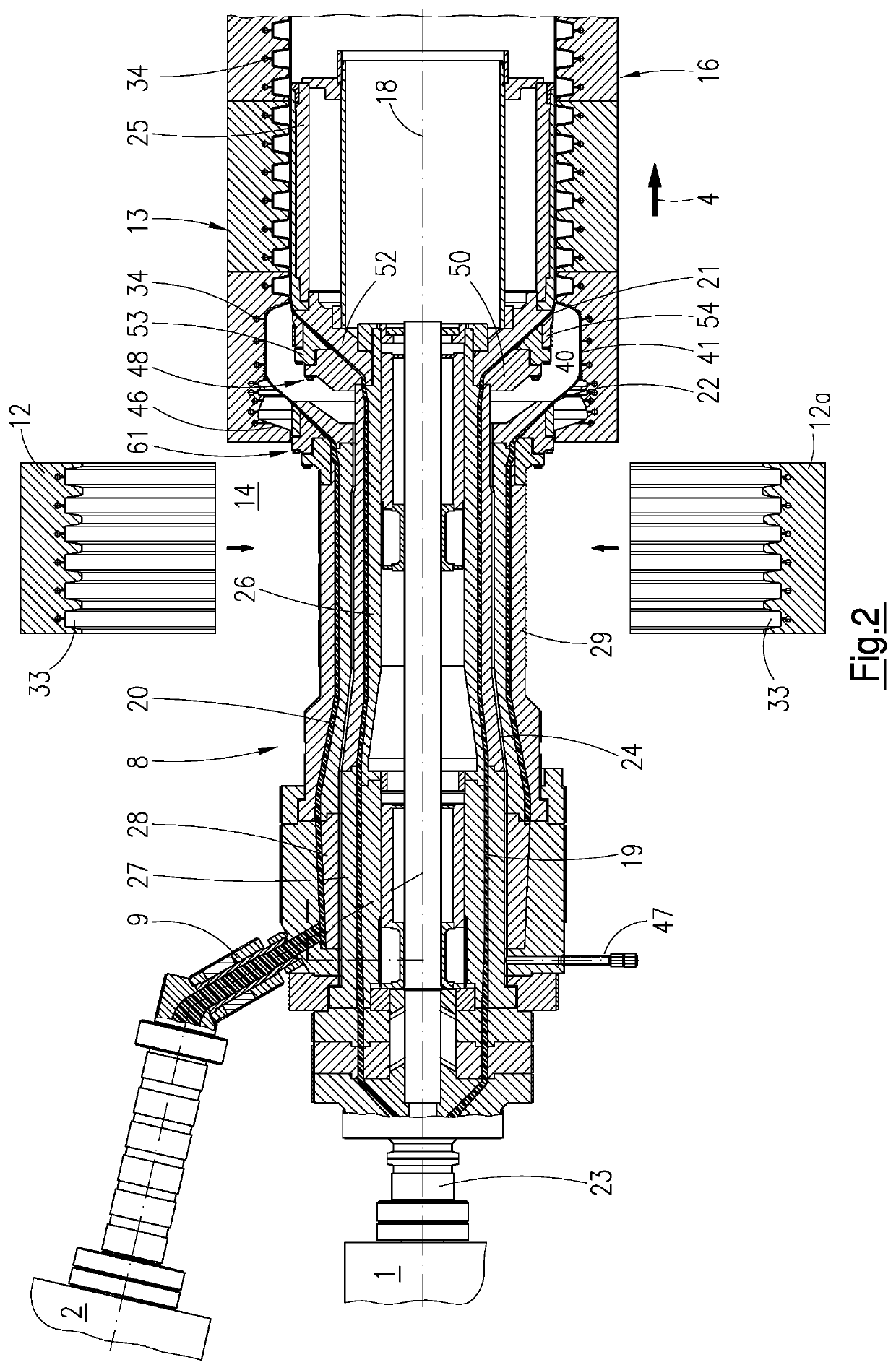
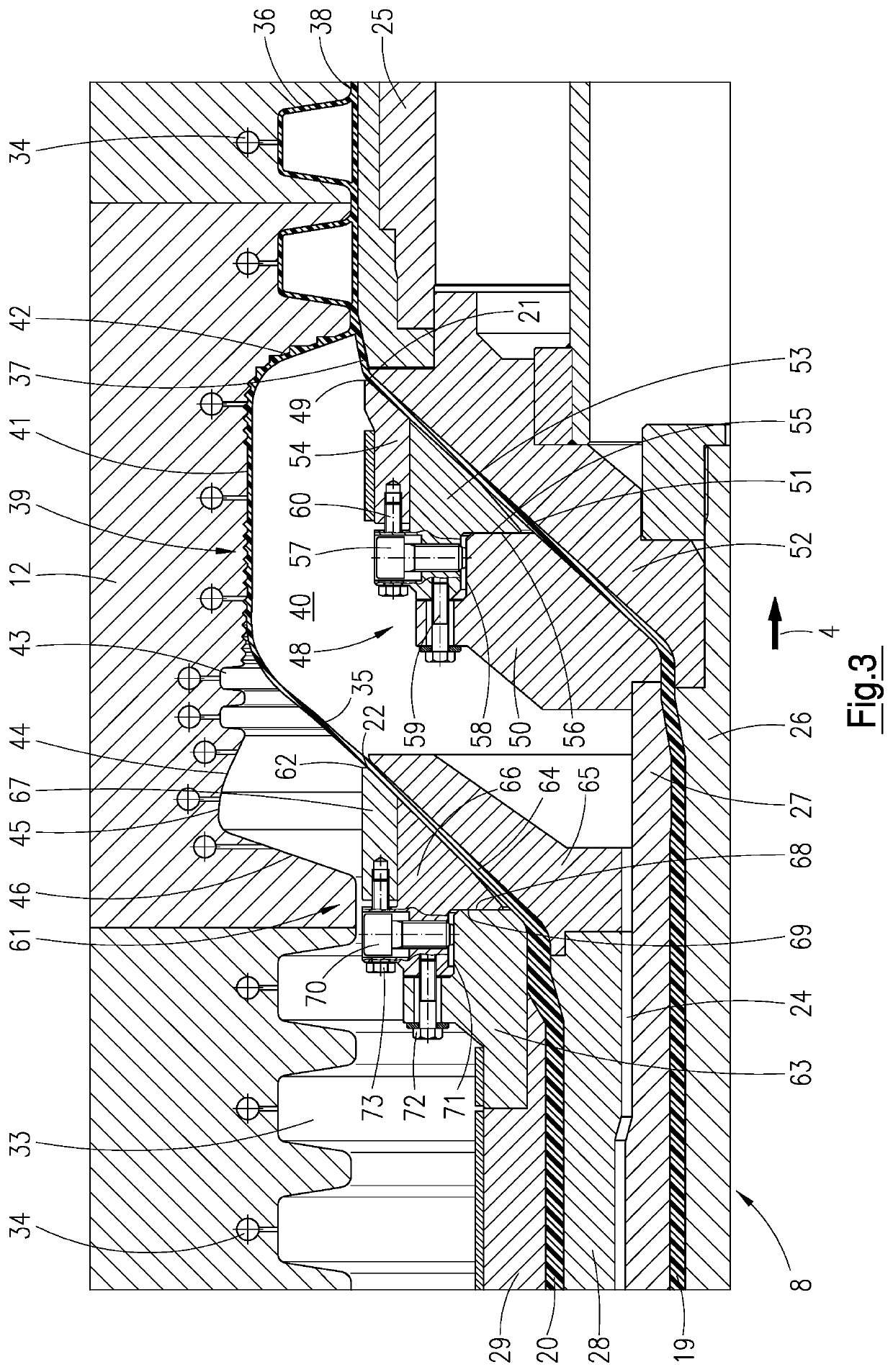
The invention aims to reduce the effort required to adjust the gap width of an injection head by designing an injection head that reduces the effort needed to adjust the radial gap of the internal nozzle. One solution to this problem is to locate the external nozzle adjustment device at the external nozzle casing and delimit the conically expanding external nozzle channel on its outside, which provides the same advantages for adjusting the gap width of the external nozzle channel as an internal nozzle adjustment device. The components of the internal nozzle only require a minimal expenditure of force to move or adjust them. The internal radial adjustment ring and the internal support ring abut against each other in a sealing manner by means of faces extending radially to the centre longitudinal axis, ensuring a reliable sealing is achieved.

Problems solved by technology

This leads to considerable sealing problems and, therefore, to the risk of operational malfunctions.
In the case of injection heads for apparatuses for the production of twin-wall pipes having large nominal widths, in particular nominal widths great-er than DN 400, the external radial nozzle centering, in particular of the internal nozzles, have a major disadvantage as the injection heads and the individual components thereof are very heavy, with the result that the entire injection head may have a weight of several tons.
This is possible only with a very high expenditure of force while requiring a complicated design so it is extremely impractical when producing twin-wall pipes having a large nominal width.

Method used


Image

  • Injection head for an apparatus for the production of a twin-wall pipe
  • Injection head for an apparatus for the production of a twin-wall pipe
  • Injection head for an apparatus for the production of a twin-wall pipe

Examples


Embodiment Construction

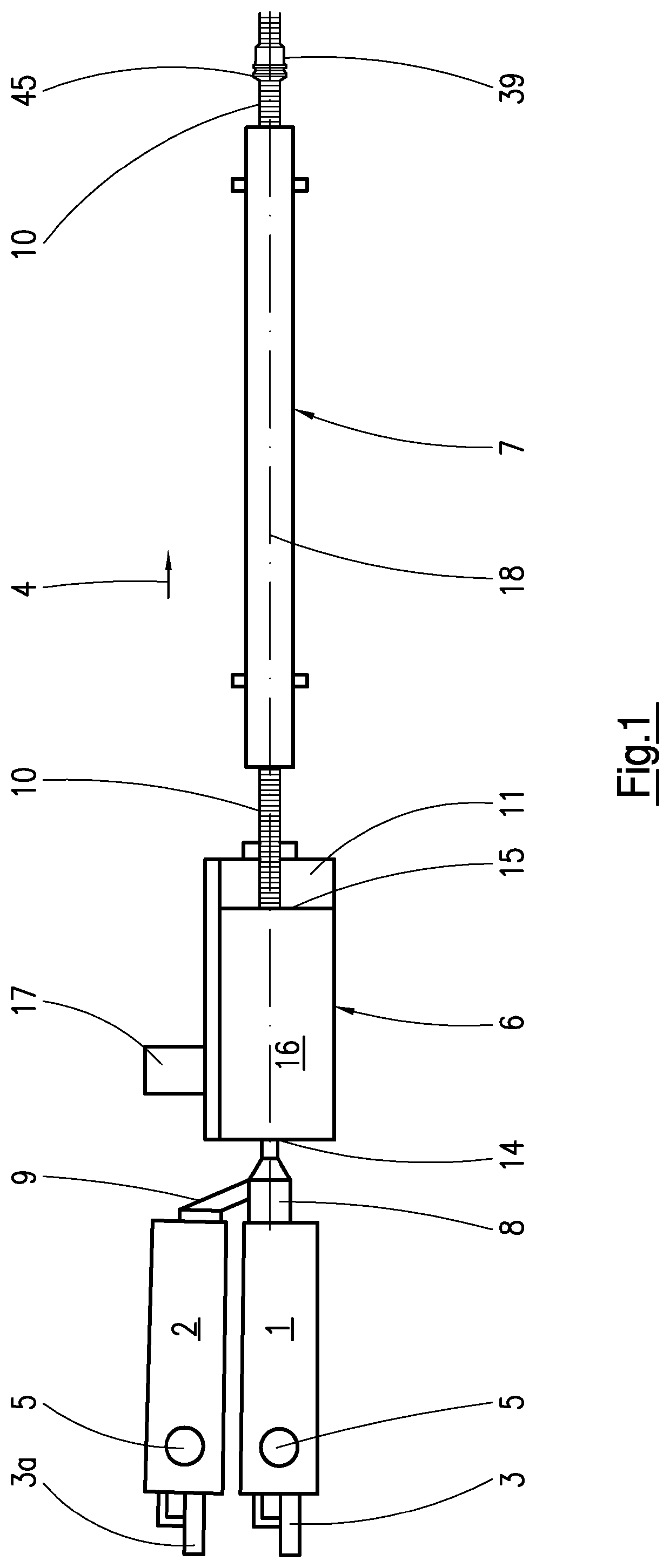
[0026]The system shown in FIG. 1 for producing twin wall pipes has two extruders 1, 2. These are in each case driven by a speed-controllable drive motor 3 or 3a, which—in relation to a conveying direction 4 of the entire system—is provided upstream in front of the supply hoppers 5 of the extruders 1, 2.

[0027]Downstream of the extruders 1, 2 in relation to the conveying direction 4, there is arranged a corrugator 6, a so-called corrugator, downstream of which is in turn arranged an additional cooling device 7. Attached to an extruder 1 arranged aligned with the corrugator 6 and the additional cooling device 7 is a cross pipe head 8, in other words an extrusion tool, which projects into the corrugator 6. The other extruder 2 arranged to the side of this extruder 1 is connected by an injection channel 9, which opens laterally into the cross pipe head 8, to the cross pipe head 8. As indicated schematically in FIG. 1, a twin wall pipe 10, which leaves the corrugator 6 in the conveying di...


PUM

PropertyMeasurementUnit
widthaaaaaaaaaa
shapeaaaaaaaaaa
gap widthaaaaaaaaaa

Abstract

An injection head for an apparatus for the production of twin-wall pipes has an external melt channel leading to an external nozzle and an internal melt channel leading to an internal nozzle. From the internal melt channel, a conically expanding internal nozzle channel leads to an internal nozzle outlet of the internal nozzle. In the region of the internal nozzle channel, an internal nozzle adjustment device is arranged by means of which the gap cross-section of the internal nozzle channel is displaceable and adjustable up to the internal nozzle outlet by radial displacement.

Description

CROSS-REFERENCES TO RELATED APPLICATIONS[0001]This application claims the priority of German Patent Application, Serial No. 10 2015 219 221.0, filed Oct. 6, 2015, pursuant to 35 U.S.C. 119(a)-(d), the content of which is incorporated herein by reference in its entirety as if fully set forth herein.FIELD OF THE INVENTION[0002]The invention relates to an injection head for an apparatus for the production of a twin-wall pipe consisting of a smooth internal pipe and an external pipe welded thereto and provided with corrugations, the injection head comprising[0003]an external melt channel extending concentrically to a centre longitudinal axis and leading to an external nozzle,[0004]an external nozzle casing delimiting the external melt channel on its side facing away from the centre longitudinal axis,[0005]an external nozzle channel leading from the external melt channel to an external nozzle outlet of the external nozzle, said external nozzle channel expanding conically,[0006]an externa...

Claims


Application Information

Patent Timeline
Patent Type & Authority Patents(United States)
IPC IPC(8): B29C45/16B29C48/13B29C48/325B29C48/09B29C49/00B29C53/30B29C45/72B29C45/20B29C48/92B29C48/335B29C48/30B29C48/18B29C48/11B29L9/00B29L23/00
CPCB29C48/18B29C45/7207B29C53/30B29C45/20B29C48/09B29C49/0021B29C48/303B29C45/1603B29C48/302B29C48/13B29C48/325B29L2023/22B29L2009/00B29C48/30B29C48/92B29C48/336B29C2948/92647B29C48/11
Inventor HEGLER, RALPH PETER
Owner HEGLER RALPH PETER
Learn More