
Ku-band diplexer

a satellite transceiver and diplexer technology, applied in the field of transceivers, can solve the problems of inability to address the electromagnetic compatibility (emc) issue, conventional diplexer topology does not provide the additional out of band rejection necessary to meet these requirements, and insertion loss limitations that affect transmit power, noise figure, gain, etc., to achieve the optimum out of band rejection and insertion loss characteristics, reduce the size of the material, and reduce the effect of loss

Active Publication Date: 2010-07-29
OMNITRACS
View PDF11 Cites 8 Cited by
  • Summary
  • Abstract
  • Description
  • Claims
  • Application Information

AI Technical Summary

Benefits of technology

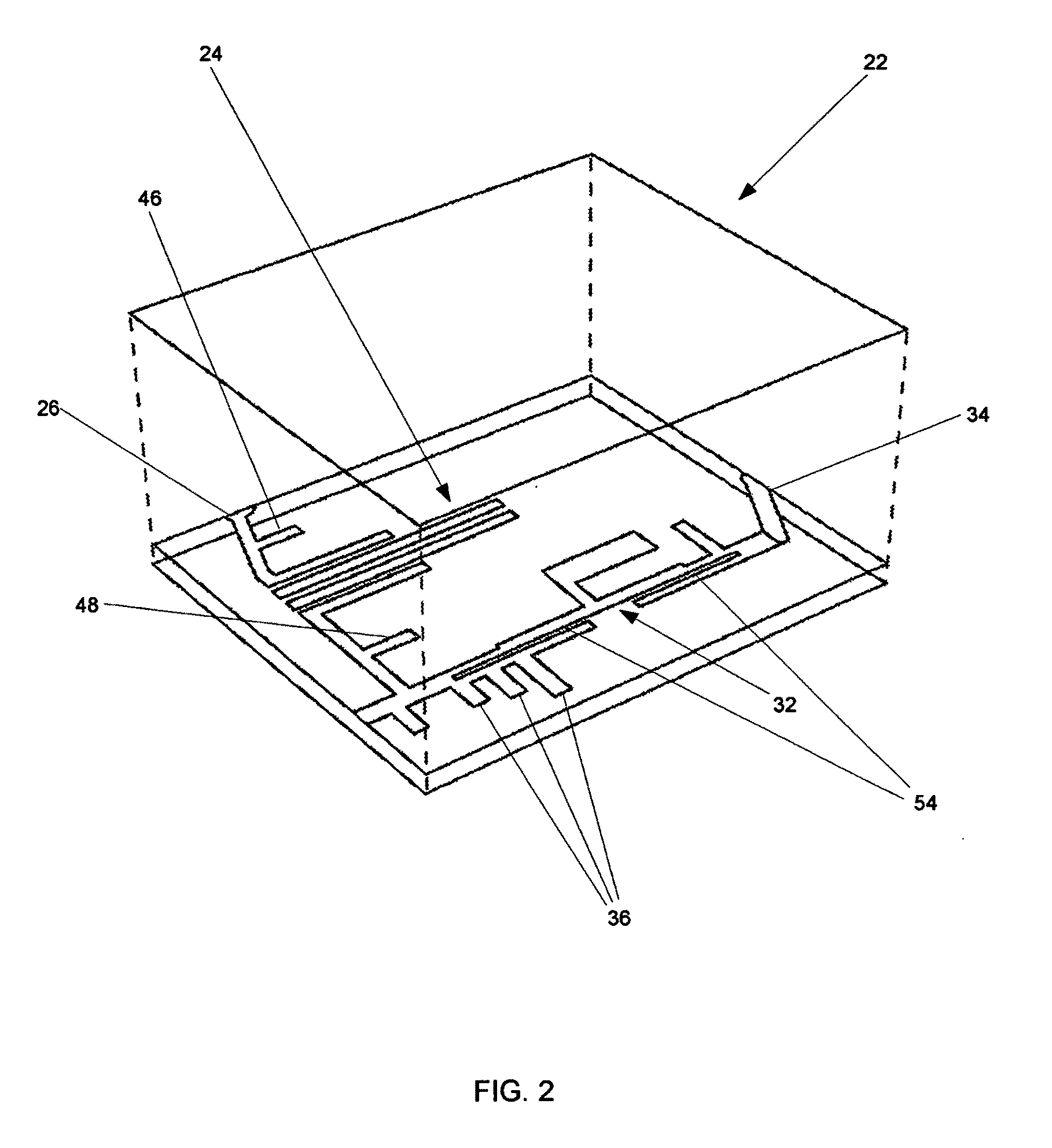
[0010]It is beneficial to have the diplexer layout on the higher dielectric low loss material, such as alumina, to reduce its size and provide optimum out of band rejection and insertion loss characteristics. The embodiments disclosed herein comprises an edge coupled band pass filter on the receive side of the diplexer using additional open circuit stubs for the receive band combined with a dual spur line band stop filter on the transmit side. The spur line filter is created by placing slots in the transmission line. The embodiment also uses open stubs in combination with the spur line filter to maximize the second harmonic suppression. The number of open stubs can be as few as one and a plurality depending on the desired bandwidth of the stop band. This diplexer accounts for close frequency spacing between transmit and receive bands, a high side local oscillator on receive channels, and insertion loss limitations that affect transmit power, noise figure, and gain. This implementation also provides sufficient isolation between transmit and receive ports so as to not degrade noise figure when the power amplifier is turned off. This is important in a half duplex system where it is common to turn off the power amplifier in receive mode.
[0011]The band stop filter topology on the transmit side combined with the additional open circuit stubs provides maximum suppression of second harmonics. This embodiment provides for cascading two spur line compact microstrip filters to increase the stop band rejection and increase bandwidth in the pass band. Additionally, the open stubs are added to notch the rejection directly in the second harmonic band.
[0012]An object of the present invention is to provide a capability to use a common antenna for both transmit and receive, provide isolation between transmit output and receive input, and maintain proper impedance match between transmit output, receive input, and the antenna. This implementation provides the additional features of second harmonic rejection of the transmit signal, as well as small size due to the higher dielectric constant of the alumina substrate. In addition, the port transitions were optimized using electromagnetic (EM) simulation tools for optimum performance.

Problems solved by technology

These prior art diplexer devices have several shortcomings such as large size and the failure to address the electromagnetic compatibility (EMC) issues of second harmonic and local oscillator radiation.
The conventional diplexer topology does not provide the additional out of band rejection necessary to meet these requirements.
This diplexer accounts for close frequency spacing between transmit and receive bands, a high side local oscillator on receive channels, and insertion loss limitations that affect transmit power, noise figure, and gain.

Method used


Image

  • Ku-band diplexer
  • Ku-band diplexer
  • Ku-band diplexer

Examples


Embodiment Construction

[0020]The word “exemplary” is used herein to mean “serving as an example, instance, or illustration.” Any embodiment described herein as “exemplary” is not necessarily to be construed as preferred or advantageous over other embodiments.

[0021]An exemplary embodiment of the present invention is shown in FIG. 2. Diplexer 22 comprises an edge coupled band pass filter 24 on receive side 26 using additional open circuit stubs or input tapped line 46 and output tapped line 48 for the receive band combined with a dual spur line band stop filter 32 on transmit side 34. Spur line filter 32 is created by placing slots 54 in the transmission line. The embodiment also uses open stubs 36 in combination with spur line filter 32 to maximize the second harmonic suppression. Although three open stubs 36 are shown in FIG. 2, the number of stubs can be modified or used depending on the bandwidth of the stop band. In the embodiment of FIG. 2, the number of stubs shown achieves a one (1) GHz stop band. T...


PUM

PropertyMeasurementUnit
Frequencyaaaaaaaaaa
Frequencyaaaaaaaaaa
Frequencyaaaaaaaaaa

Abstract

A compact Ku band microwave diplexer configured as a three port surface mount component on a miniature alumina substrate. Input signals occurring at a common port having frequencies within a first pass band are passed to a second port while being isolated from signals occurring at a third port. Signals occurring at the third port are passed to the common port while being isolated from the signals at the second port. A microstrip dual spur line filter is used combined with open circuit stubs to provide enhanced second harmonic suppression on the transmit side, while using a coupled line microstrip filter on the receive side. This approach allows for compact size and automated component assembly through pick and place and reflow manufacturing techniques.

Description

CLAIM OF PRIORITY UNDER 35 U.S.C. §119[0001]The present application for patent claims priority to Provisional Application No. 60 / 843,342, filed on Sep. 7, 2006, entitled Diplexer Design and Provisional Application No. 60 / 844,180, filed on Sep. 12, 2006, entitled Diplexer Design, and assigned to the assignee hereof and hereby expressly incorporated by reference herein.BACKGROUND[0002]1. Field of the Invention[0003]The present invention relates to transceivers and more particularly to a diplexer for a Ku-band satellite transceiver.[0004]2. Background of the Invention[0005]In transceiver design, there is a necessity to keep transmit and receive channels isolated. This is done using a diplexer at the front end or antenna port. This apparatus needs to provide isolation between transmit and receive ports, as well as filtering of unwanted local oscillator emissions and second harmonic products from the transmitter. This all needs to be accomplished while still maintaining a minimal loss an...

Claims


Application Information

Patent Timeline
IPC IPC(8): H01P5/12
CPCH01P5/085H05K1/0243H05K1/116Y10T29/49139H05K2201/09718H05K2201/09809H05K3/3447H01P1/2135
Inventor DEVEREUX, JEFFBERGER, FRITZ GERDJOHNSTON, WILLIAM A.TASSOUDJI, MOHAMMAD ALIALDERN, SCOTT
Owner OMNITRACS
Learn More