
Trench mosfet device with low gate charge and the manfacturing method thereof

a technology of gate charge and trench mosfet, which is applied in the direction of basic electric elements, semiconductor devices, electrical apparatus, etc., can solve problems such as energy loss, and achieve the effects of reducing overlapped area, resistivity, and resistan

Inactive Publication Date: 2010-07-08
NIKO SEMICON
View PDF5 Cites 18 Cited by
  • Summary
  • Abstract
  • Description
  • Claims
  • Application Information

AI Technical Summary

Benefits of technology

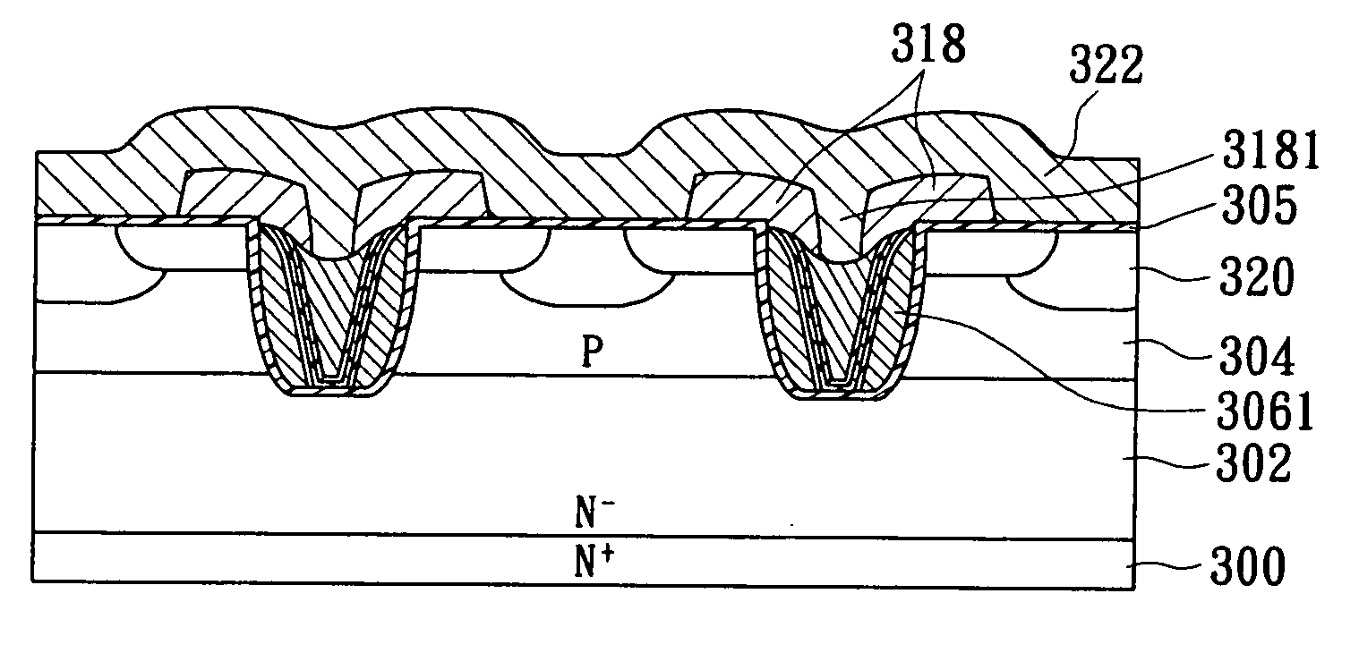
[0007]In view of the aforementioned issues, the present invention provides a method for manufacturing trench MOSFET device with low gate charge (Qgd), which is capable to reduce the overlapped area between the poly-silicon gate and the bottom surface of the trench so as to lower down capacitance between the gate and the drain (Cgd) as well as gate charge (Qgd). Furthermore, a metal-salicide layer with lower resistivity is provided for compensating the rising of gate resistance due to a smaller cross-section area of the poly-silicon gate. Accordingly, a trench MOSFET device with low switching loss is provided.
[0011]As mentioned above, formation of the ploy-silicon spacer on the side-wall of the trench is capable for restricting the overlapped area between the poly-silicon gate and the bottom surface of the trench. The rising resistance due to a smaller cross-section area of the poly-silicon gate can be compensated by the metal-salicide layer with lower electric resistivity on the poly-silicon spacer or an extra poly-silicon structure connected to the ploy-silicon spacer. Therefore, the trench MOSFET device in the present invention can be adopted in the situation of increased switching rate and the switching loss can be reduced to improve the operational efficiency. That is, the trench MOSFET device of the present invention is suitable for high frequency application.

Problems solved by technology

However, the narrower gate may result in a greater gate resistance to cause energy loss.

Method used


Image

  • Trench mosfet device with low gate charge and the manfacturing method thereof
  • Trench mosfet device with low gate charge and the manfacturing method thereof
  • Trench mosfet device with low gate charge and the manfacturing method thereof

Examples


Embodiment Construction

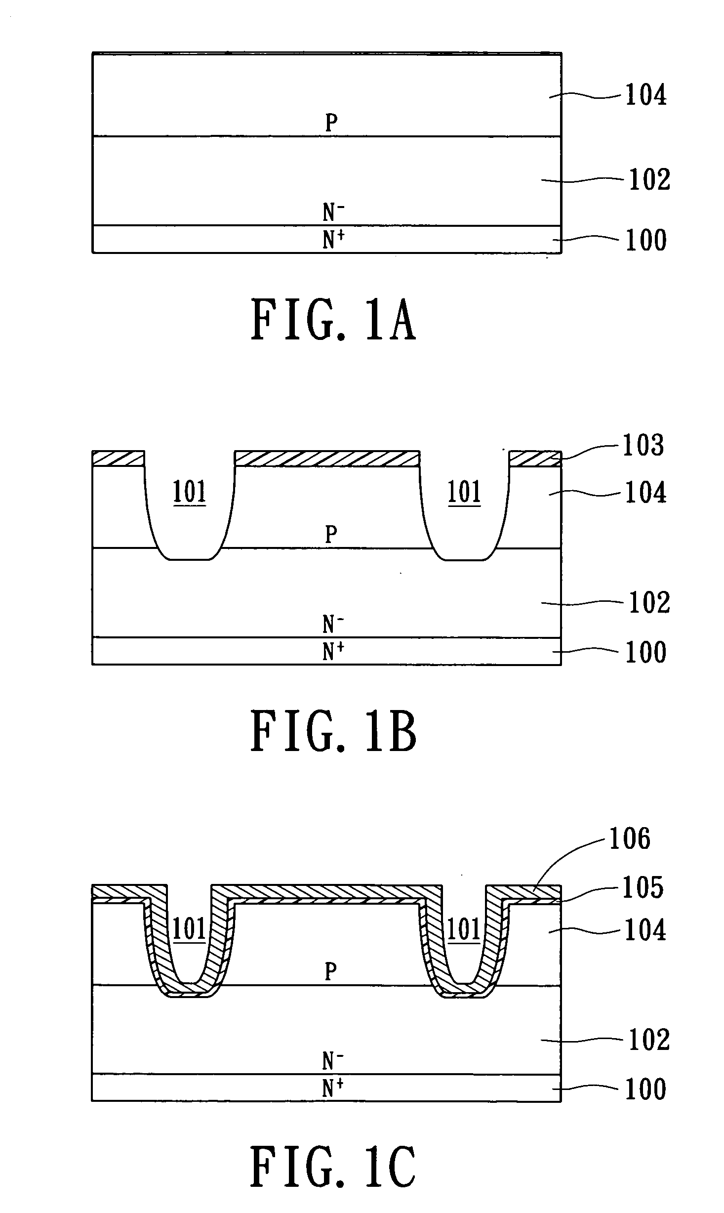
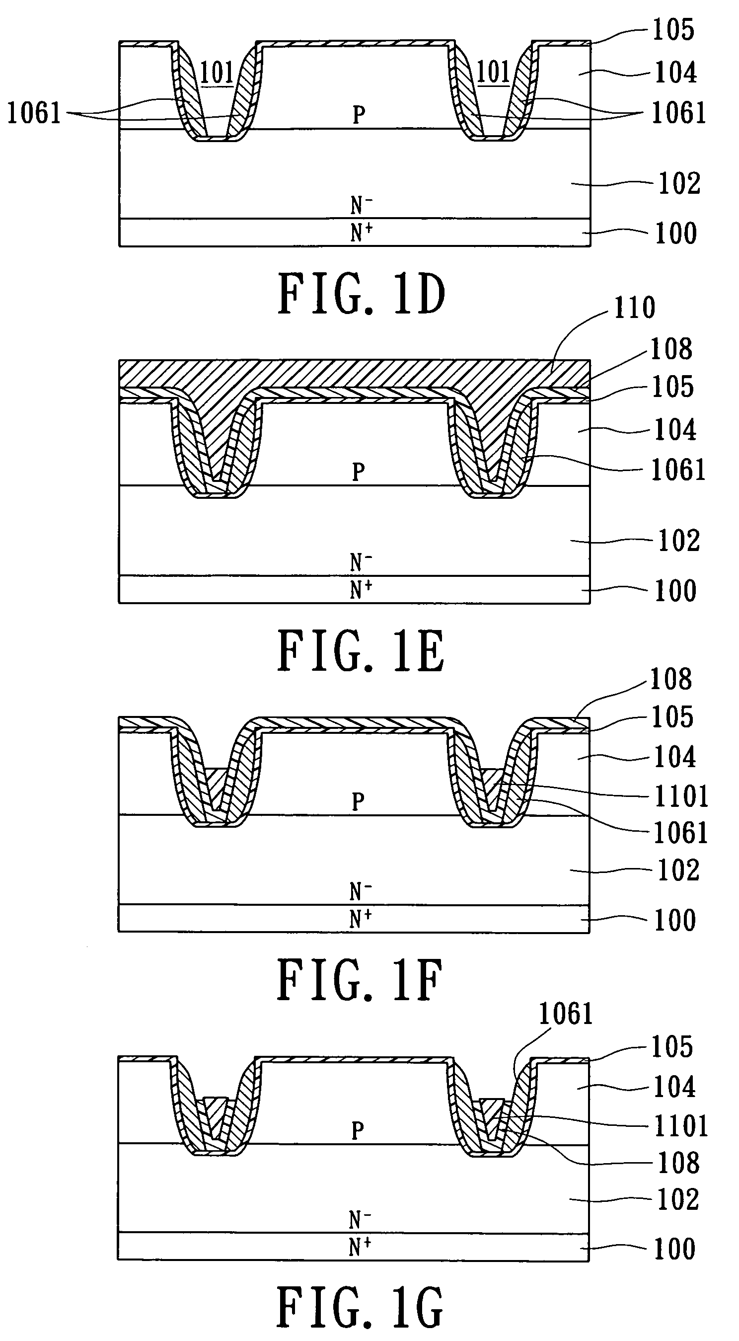
[0016]The present invention provides a trench MOSFET device with low gate charge and a method for manufacturing the same. The manufacturing method of the present invention has the ploy-silicon spacer formed in the trench for decreasing the overlapped area between the ploy-silicon gate and the bottom surface of the trench and adopts metal-salicide with low electric resistivity so as to achieve the objects of lowering the capacitance between the gate and the drain (Cgd) as well as the gate resistance. Therefore, switching loss of the trench MOSFET device can be reduced. Please refer to FIGS. 1A to 1M, the first embodiment of the manufacturing method according to the present invention is shown. The manufacturing method includes the following steps.

[0017]Firstly, as shown in FIG. 1A, a substrate 100 of first conductivity type is provided. An epitaxial layer 102 of first conductivity type is formed on the substrate 100 and a body region 104 of second conductivity type is formed in the up...


PUM


Abstract

A method for manufacturing trench MOSFET device with low gate charge includes the steps of providing a substrate of first conductivity type; forming an epitaxial layer of first conductivity type on the substrate; forming a body region of second conductivity type in the epitaxial layer, the body region extends downwards from the surface of the epitaxial layer; forming a plurality of trenches in the epitaxial layer, the body region having the trenches formed therethrough; forming a first insulating layer on the body region and on an inner surface of each trench; forming a ploy-silicon spacer on the first insulating layer on an inner side-wall of each trench; filling a dielectric structure in the lower portion of each trench; and filling a ploy-silicon structure on top of the dielectric structure in each trench. Through the trench MOSFET device, the gate capacitance and resistance thereof are reduced so the performance is increased.

Description

BACKGROUND OF THE INVENTION[0001]1. Field of the Invention[0002]The present invention relates to a method for manufacturing trench MOSFET device and the structure thereof, in particular, to a method for manufacturing trench MOSFET device with low gate charge.[0003]2. Description of Related Art[0004]Trench metal-oxide-semiconductor (MOS) device includes a gate electrode inside a trench which extends downward from a surface of the semiconductor substrate. The current flow by the gate electrode of the trench MOS device is substantially along a vertical direction. Therefore, cell pitch of the MOS devices can be reduced. In present, there are various MOS devices available in the market, such as metal-oxide-semiconductor field-effect transistor (MOSFET), insulated-gate bipolar transistor (IGBT), thryistor, and so on.[0005]As the operating frequency of the power switching devices such as MOSFET increased, improvement of switching efficiency becomes more and more important. How to design a ...

Claims


Application Information

Patent Timeline
IPC IPC(8): H01L29/78H01L21/28
CPCH01L21/2815H01L29/407H01L29/7813H01L29/4933H01L29/66734H01L29/42376
Inventor HSU, HSIU-WENNI, CHUN WETU, KAO- WAY
Owner NIKO SEMICON
Learn More