Eureka AIR delivers breakthrough ideas for toughest innovation challenges, trusted by R&D personnel around the world.

A method for operating a valve

A technology of valve operation and components, applied in the direction of valve details, multi-way valves, valve devices, etc., can solve problems such as inconvenient and slow

Inactive Publication Date: 2012-05-09
DANFOSS AS
View PDF13 Cites 10 Cited by
  • Summary
  • Abstract
  • Description
  • Claims
  • Application Information

AI Technical Summary

Problems solved by technology

However, simply closing a valve slowly enough to prevent or reduce water hammer is not possible in some circumstances, or at least inconvenient or inappropriate, for example because the normal operation of the valve requires it to be closed by a certain velocity

Method used


Image

  • A method for operating a valve
  • A method for operating a valve
  • A method for operating a valve

Examples


Embodiment Construction

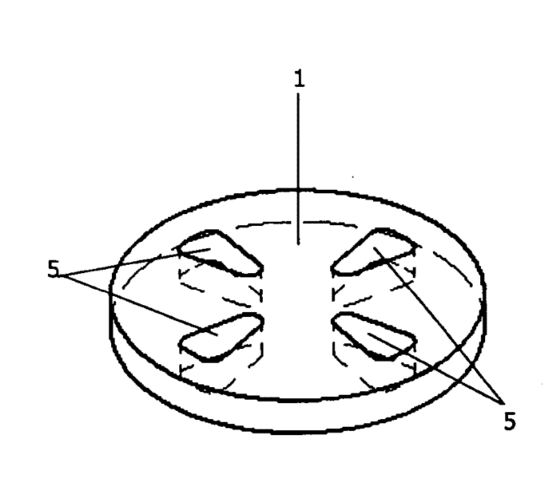
[0041] Figure 1a A first valve part 1 for a valve suitable for carrying out the method according to an embodiment of the invention is shown. The first valve member 1 is in the form of a substantially disc, and it has four openings 2, each of substantially circular cross-section, formed therein as a trough-going bore extending through the disc .

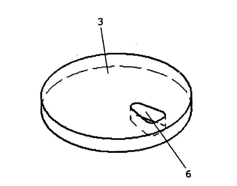
[0042] Figure 1b A second valve part 3 for a valve suitable for carrying out the method according to an embodiment of the invention is shown. The second valve member 3 is in the form of a substantially circular disk having a diameter substantially equal to Figure 1a The diameter of the first valve part 1. therefore, Figure 1a The first valve part 1 and Figure 1b The second valve part 3 is adapted to form the part of the same valve and cooperates in defining the opening of the valve. This will be referenced below Figure 2a-2f is described in more detail.

[0043] The second valve part 3 is provided with an opening 4 in the ...


PUM


Abstract

A method for operating a valve comprising a first valve part (1) having at least one opening (2) and a second valve part (3) having at least one opening (4) formed is disclosed. The first (1) and second (3) valve parts are adapted to perform relative movements, the relative position of the opening(s) (2) of the first valve part (1) and the opening (s) (4) of the second valve part (3) defining an opening degree of the valve by means of an overlapping area of the openings (2, 4). The method comprises the step of moving the first valve part (1) and / or the second valve part (3) from a position defining a maximum opening degree of the valve towards a position defining a minimum opening degree of the valve in such a manner that the velocity of the relative movement between the first valve part (1) and the second valve part (3) is decreased as the overlapping area decreases.

Description

technical field [0001] The present invention relates to a valve operating method, in particular to a valve for a refrigeration system. More particularly, the method of the present invention allows the valve to be operated in such a way that pressure pulsations in the fluid system in which the valve is inserted are considerably reduced, or even eliminated. Background technique [0002] When the valve of the fluid system is closed, the sudden stop of fluid flow creates a reverse flow in the system. The reverse flow causes a pulsating high pressure shock wave or transient. This shock wave produces impact noise and fluid system piping vibration. This is called "water hammer". Impact noise is undesirable, especially in fluid systems where valves are repeatedly opened and closed. Additionally, vibration may cause damage to piping and / or other parts of the fluid system. [0003] It is known that water hammer can be reduced by slowly closing the valve. However, simply closing ...

Claims


Application Information

Patent Timeline
Patent Type & Authority Applications(China)
IPC IPC(8): F16K47/02F25B41/06F16K11/074
CPCF16K11/074F25B41/062F16K47/023Y10T137/0318F25B41/325
Inventor C. 泰博
Owner DANFOSS AS
Why Eureka
Eureka Blog
Learn More